
ベーパーポリッシュは、対応するCNCプラスチックの外表面を短時間軟化・再流動させることで、透明性と見かけの平滑性を向上させることができます。. これはツールパスエラー、深い傷、内部応力、不適切な材料選択、または制御された露出を妨げる形状を修正するものではありません。最良の結果は、加工、応力管理、エッジ状態、研磨ルート、光学検査を一つのプロセスとして設計することから得られます—ベーパーポリッシュを万能な救済手段として扱うことからではありません。.
なぜ透明プラスチックは加工後に曇るのか
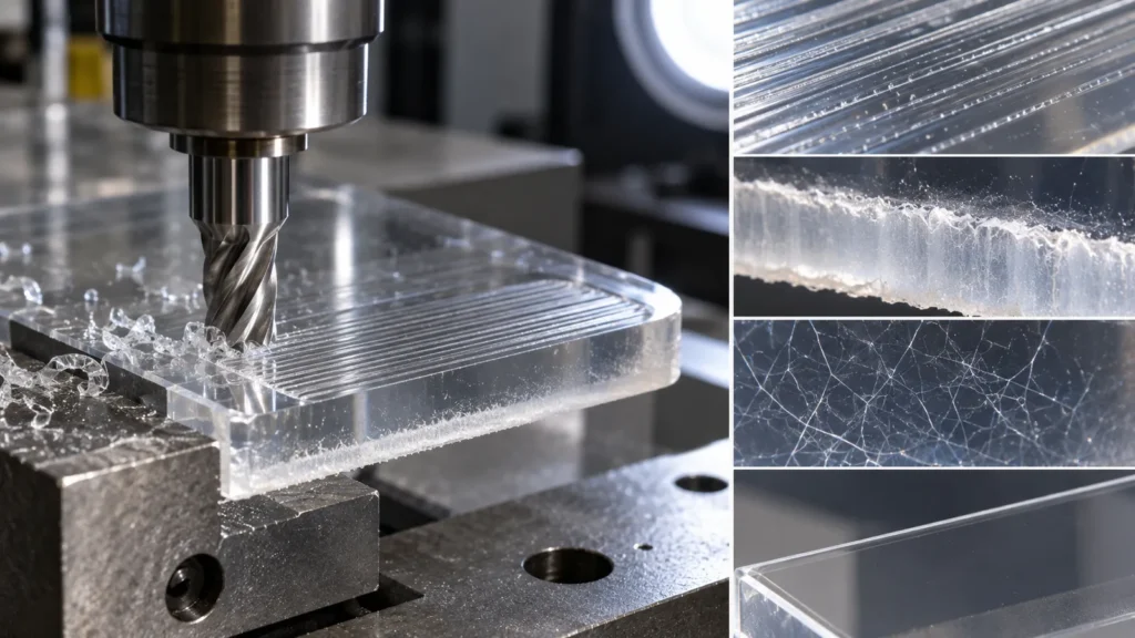
加工痕
送り目と工具形状が規則的な曇り外観を生み出します。.
熱と応力
局所的な軟化、割れ、または閉じ込められた応力が、仕上げ中または仕上げ後に現れることがあります。.
材料の挙動
異なるポリマーは、切削工具、クーラント、溶剤、研磨ルートに対して異なる反応を示します。.
部品がすでに割れている、クレージングしている、寸法的に不安定である、または非対応のポリマーで作られている場合、ベーパーポリッシュは問題を隠すどころか増幅させる可能性があります。仕上げを確定する前に、 CNC加工材料ガイド を通じて材料選択を見直してください。.
ベーパーポリッシュが実際に変えるもの
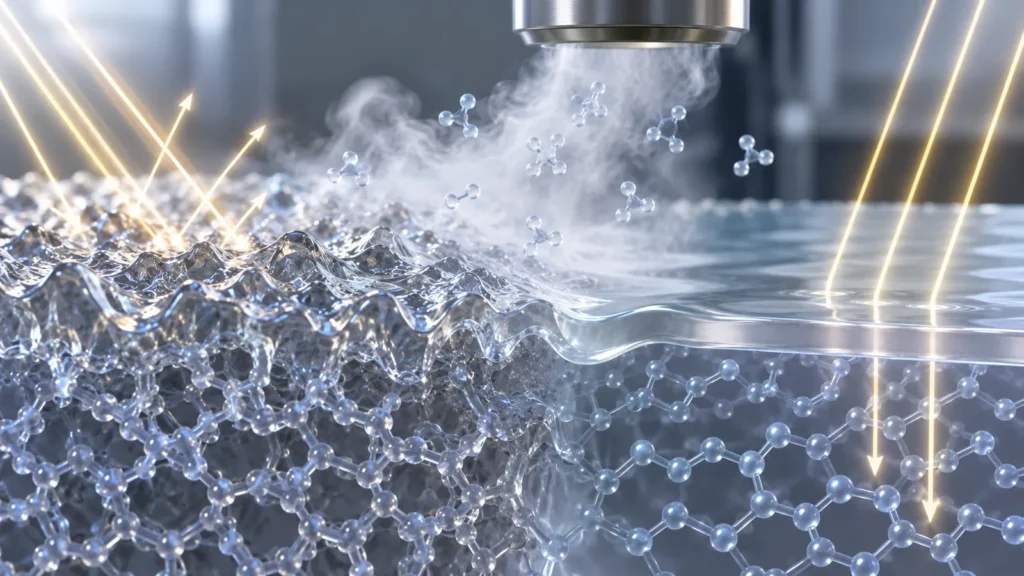
同じメカニズムがリスクも生み出します。過度の曝露は、エッジを丸め、細部を軟化させ、薄い形状を歪め、小さな開口部を閉塞させ、光沢を不均一に変化させ、クレージングによって応力を露呈させる可能性があります。形状、材料ロット、先行する機械加工、洗浄、温度、治具固定、曝露、乾燥のすべてが結果に影響します。.
表面リフローはまた、欠陥の根本原因を除去することなく、その見え方を変えることがあります。ビビリによる谷は光沢を帯びても、光学的な歪みが残ることがあります。応力がかかったコーナーは検査時に許容範囲に見えても、後で洗浄薬品や組立荷重に曝されるとクレージングを生じることがあります。したがって、プロセスレビューには即時の外観と遅延した使用挙動の両方が必要です。.
チャネルや密閉キャビティでは、アクセスは問題の半分にすぎません。プロセスは予測可能な排出、乾燥、清浄度も支える必要があります。隠れた通路に残留物が残る場合や、処理が流体接触要件を変える場合、きれいな外観は許容できません。.
透明性より先に適合性
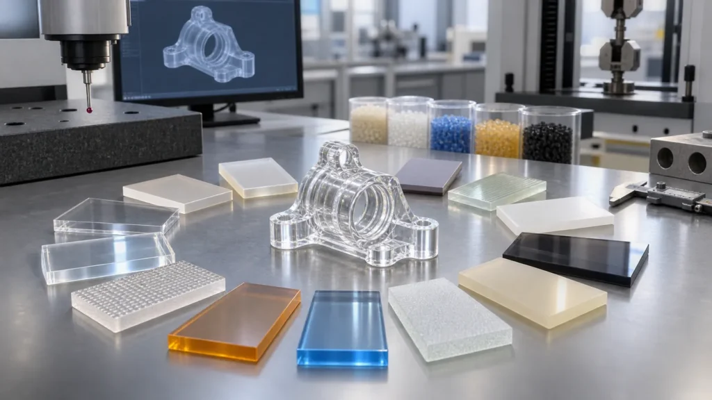
| 確認すべき入力 | 重要な理由 | 提供すべき証拠 |
|---|---|---|
| 正確な樹脂とグレード | 化学反応と応力割れは配合によって異なる | 材料呼称とサプライヤーデータ |
| 色と添加剤 | Pigments, fillers, and reinforcement can change appearance | Production-intent stock or representative coupon |
| Prior heat and stress history | Residual stress can become visible during chemical exposure | Machining route, stock form, and any annealing requirement |
| Service contact | Optical, medical, fluid, vacuum, or chemical use may restrict residues and methods | Application, cleaning, regulatory, and compatibility requirements |
Traceability becomes important when clarity is part of product performance. Keep production stock consistent with the approved trial, and record any resin-source or grade change before processing. Two plastics sold under a similar family name may not behave identically because formulation and stress history differ.
When the part will contact alcohols, cleaners, fuels, adhesives, or sterilization media, include that exposure in validation. A surface that survives polishing may still be incompatible with the chemicals encountered later in service.
The Geometry Risk Map
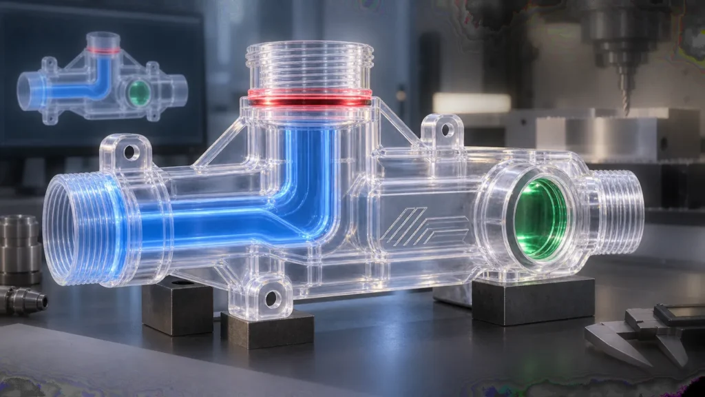
- Red—protect or exclude: sealing lands, precision bores, threads, sharp optical edges, calibrated flow openings, engraved scales, and adhesive-bond areas.
- Amber—validate by sample: thin walls, ribs, deep recesses, intersections, snap features, and regions with heavy stock removal.
- Green—primary polish zones: accessible viewing windows and broad surfaces with enough dimensional freedom.
The map also supports fixturing and inspection. A housing may need clarity only through one window, while the flange, ports, and mounting bosses must preserve their machined condition. Selective requirements are easier to control than “polish entire part.”
Vapor, Flame, or Mechanical Polishing?
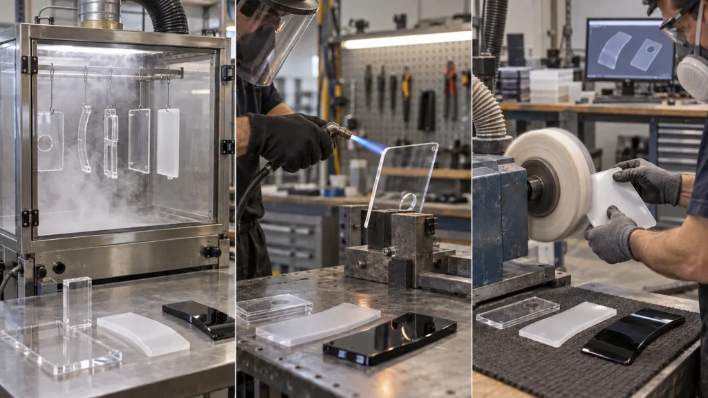
A hybrid route may use fine machining followed by controlled polishing. The site’s CNC post-processing overview helps frame this as part of the full manufacturing route rather than a stand-alone cosmetic operation.
Clarity Begins at the Cutting Tool
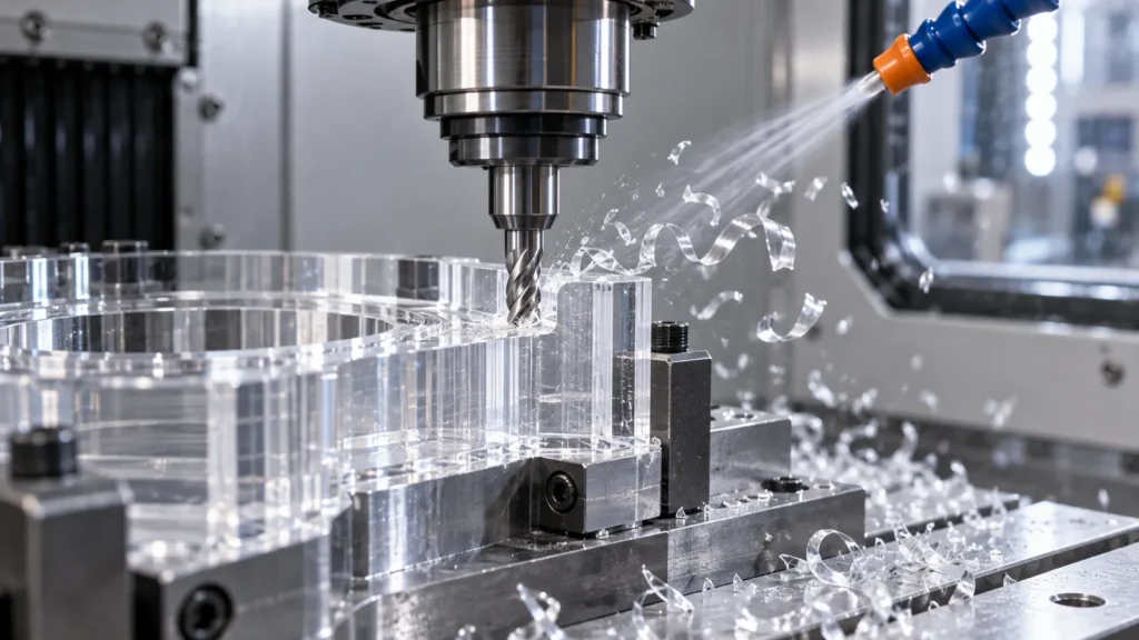
A useful process sequence
- Verify material identity and condition before machining.
- Rough the part while controlling heat and residual stress.
- Allow an appropriate stabilization step where the material and geometry require it.
- Finish critical geometry with sharp tooling and a stable path.
- Remove burrs without damaging optical zones.
- Clean using a method compatible with the polymer and polish route.
- Run a representative polishing trial before locking production settings.
Define “Clear” So It Can Be Inspected
| Acceptance category | 考えられる管理方法 |
|---|---|
| Functional visibility | Readability or target recognition through the production geometry |
| Visual defects | Scratch, haze, bubble, streak, burn, inclusion, and edge limits by zone |
| Dimensions | Post-polish measurement of interfaces and wall geometry |
| Surface and cleanliness | Agreed roughness, residue, rinse, drying, and packaging criteria |
For critical projects, approve a polished first article and record the inspection conditions. JUCHENG’s 品質管理の概要 provides the context for dimensional and visual verification.
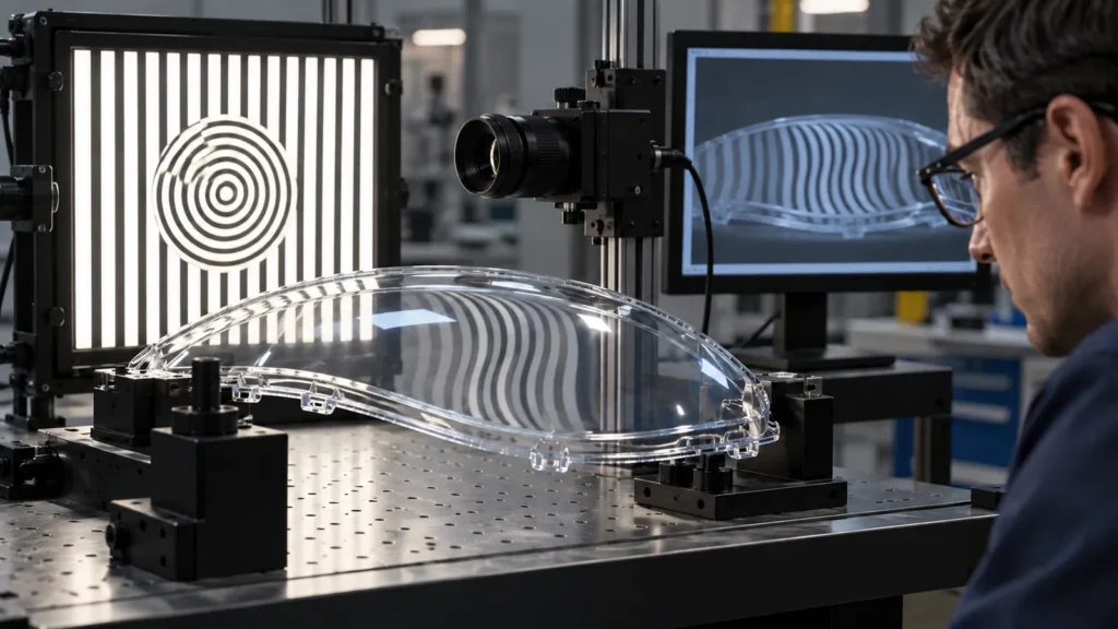
Do not judge a curved window with the same method as a flat coupon. Curvature, wall thickness, viewing angle, and internal reflections can make a conforming surface look distorted. Whenever possible, inspect through the production geometry using the real target or a representative optical setup.
Photography can document gross defects, but camera exposure and lighting can hide haze or exaggerate scratches. Physical reference parts remain valuable for cross-border purchasing because they reduce ambiguity between words such as clear, transparent, glossy, and optical.
The RFQ Package for a Clear CNC Plastic Part
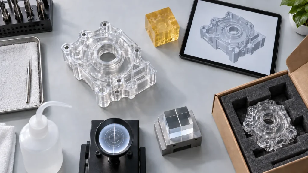
This package allows the supplier to judge whether vapor polishing is suitable, whether a machining-first improvement is enough, or whether another material or manufacturing route would lower risk.
Questions That Prevent Expensive Rework
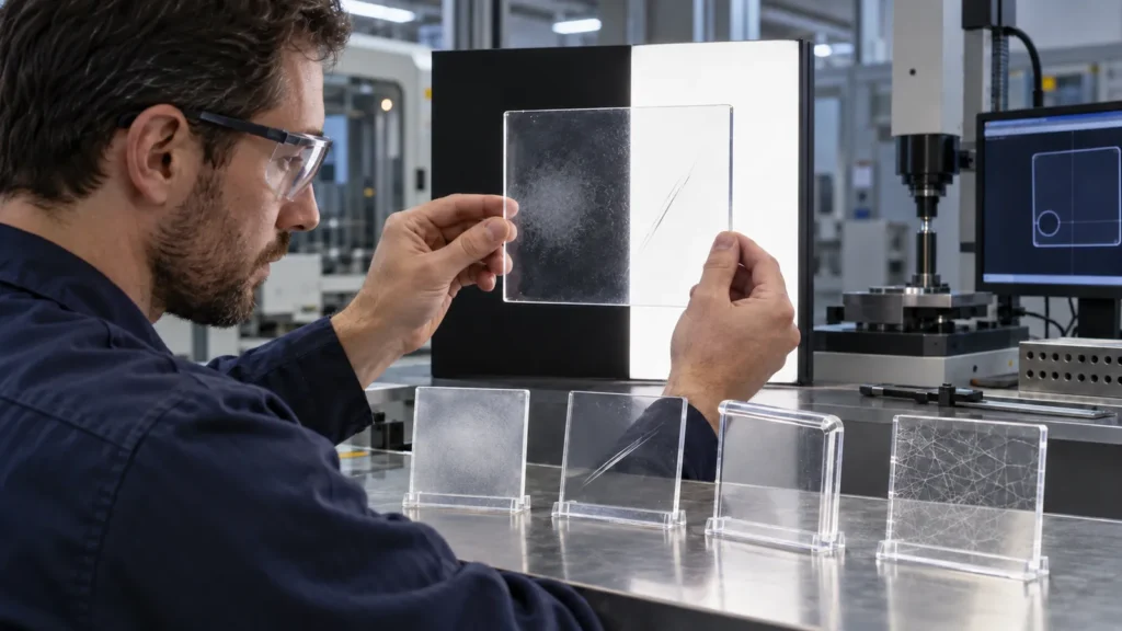
No. Suitability depends on the exact polymer grade, additives, stress condition, geometry, application, and available controlled process. Confirm compatibility using production-intent material.
Will vapor polishing remove deep scratches?
It is intended to reflow the near surface, not erase deep damage without dimensional consequence. Deep scratches should be prevented or reduced before polishing, and critical wall thickness or geometry must still be protected.
Can a polished part still crack later?
Yes. Residual machining stress, incompatible chemicals, assembly load, sharp corners, temperature, and service exposure can contribute to delayed crazing or cracking. Surface clarity does not prove long-term stress resistance.