
Einleitung: Die Präzisionskunst der GPU-Kühlblock-Bearbeitung
In der hochgradig kompetitiven Welt der PC-Leistung, in der jedes Frame und jedes Megahertz zählt, ist der Kampf gegen die Wärme unerbittlich. Im Zentrum dieses thermischen Krieges steht eine Komponente von bemerkenswerter Ingenieurskunst: der GPU-Kühlblock. Er ist mehr als nur ein Stück Metall – er ist ein akribisch gefertigtes Wunderwerk der Mikrotechnik, dessen Leistung von der exakten Wissenschaft seiner Herstellung bestimmt wird. Der Prozess der GPU-Kühlblock-Bearbeitung ist nicht bloß ein Fertigungsschritt; er ist die grundlegende Kunst, die Rohmaterialien in die primäre Schnittstelle zwischen einem glühend heißen Grafikprozessor und der Kühlflüssigkeit verwandelt, die ihn bändigt. Diese Präzisionskunst balanciert Strömungsdynamik, Wärmeleitfähigkeit und mechanische Integrität aus und erfordert Toleranzen, die in Mikrometern gemessen werden. Die Reise von einem massiven Block aus Kupfer oder Aluminium zu einem komplexen Labyrinth aus Kanälen und Lamellen ist ein Zeugnis fortschrittlicher Fertigung, bei der die Qualität des Schnitts direkt in die Stille, Stabilität und Übertaktungsreserven eines High-End-Gaming-Rigs oder einer Workstation übersetzt wird.
Was ist ein GPU-Kühlblock? Anatomie und Kernfunktion
Ein GPU-Kühlblock, in Custom-Wasserkühlkreisläufen oft als Water Block bezeichnet, ist ein Wärmetauscher mit direktem Kontakt. Seine Kernfunktion besteht darin, Abwärme vom Grafikprozessor (GPU)-Die sowie von zugehörigen Komponenten wie VRAM und VRMs aufzunehmen und effizient an ein fließendes Kühlmittel abzugeben. Anders als sperrige Luftkühler erreicht er dies durch innigen Metall-auf-Metall-Kontakt und optimierte Flüssigkeitsströmungswege.
Anatomisch besteht ein typischer Vollabdeckungs-GPU-Block aus mehreren Schlüsselschichten:
- Kaltplatte: Dies ist das Herzstück des Blocks. Es ist eine flache, bearbeitete Metallplatte, die direkt auf dem GPU-Chip sitzt. Ihre Unterseite weist ein präzise bearbeitetes Array aus Mikrolamellen, Stiften oder Kanälen auf, die eine enorme Oberfläche für die Wärmeübertragung an das Kühlmittel schaffen.
- Strahlaufprall- oder Verteilerplatte: Oft in das Design der Kaltplatte integriert oder als separate Schicht ausgeführt, steuert diese Komponente den Kühlmittelstrom. Sie verwendet eine Reihe von Einlässen und Mikrodüsen, um Kühlmittel gezielt auf die heißesten Bereiche der Kaltplatte zu leiten, Grenzschichten aufzubrechen und den Wärmeaustausch zu maximieren.
- Hauptgehäuse oder Deckplatte: Diese Strukturkomponente dichtet die Kühlkammer ab. Sie enthält die Einlass- und Auslassanschlüsse für die Kühlmittelschläuche und weist oft ästhetische Elemente wie Acrylfenster oder aufwendig CNC-gefräste Designs auf. Sie muss steif genug sein, um Klemmdruck und internem Flüssigkeitsdruck standzuhalten, ohne sich zu verformen.
- Befestigungsmaterial und thermische Schnittstelle: Ein System aus Schrauben, Backplates und Abstandshaltern gewährleistet einen gleichmäßigen, sicheren Anpressdruck. Zwischen Kühlplatte und GPU-Die wird eine Hochleistungs-Wärmeleitpaste oder ein Pad aufgetragen, um mikroskopische Unebenheiten auszufüllen und eine optimale Wärmeleitung zu gewährleisten.
Im Wesentlichen ist der Block ein abgedichtetes, unter Druck stehendes Mikrokanalsystem, in dem das Kühlmittel gezwungen wird, Wärme so schnell wie möglich aufzunehmen, bevor sie zu einem Radiator abgeführt wird. Die Effizienz dieses gesamten Systems entsteht im Zerspanungsprozess.
Die entscheidende Rolle der Zerspanung für die Leistung der Flüssigkeitskühlung
Der Leistungsunterschied zwischen einer durchschnittlichen und einer außergewöhnlichen Flüssigkeitskühlungslösung wird fast vollständig während der Zerspanung geschmiedet. Diese Phase bestimmt die grundlegenden physikalischen Eigenschaften, die die thermische und hydraulische Leistung bestimmen. Drei zerspanungsabhängige Faktoren sind von größter Bedeutung: Oberflächenebenheit, Kanalgeometrie und Dichtungsintegrität.
Erstens ist die Ebenheit der Kontaktfläche der Kühlplatte nicht verhandelbar. Ein GPU-Die hat typischerweise nur eine Fläche von wenigen hundert Quadratmillimetern. Jede mikroskopische Verformung oder Unebenheit in der Kühlplatte erzeugt Luftspalte, die schreckliche Wärmeisolatoren sind. Hochpräzise Zerspanung und anschließendes Läppen gewährleisten eine nahezu perfekt ebene Oberfläche, sodass das thermische Schnittstellenmaterial eine dünne, gleichmäßige Schicht für einen ungehinderten Wärmeübergang bilden kann.
Zweitens ist die Geometrie der internen Kühlstrukturen – der Lamellen, Pins und Kanäle – ein direktes Produkt der Zerspanungsfähigkeit. Die Dichte, Höhe und Dicke dieser Merkmale definieren die thermische Leistung und den Strömungswiderstand des Blocks. Feinere, dichtere Mikrolamellen bieten mehr Oberfläche für den Wärmeaustausch, behindern jedoch den Kühlmittelfluss und erfordern mehr Pumpendruck. Der Zerspanungsprozess muss diese filigranen Merkmale mit scharfen, sauberen Kanten und gleichbleibenden Abmessungen herausarbeiten; Grate oder Abweichungen können Strömungstoträume erzeugen, den Druckabfall erhöhen und Luftblasen einschließen, was die Effizienz stark beeinträchtigt.
Schließlich definiert die Zerspanung die Dichtflächen. Die Paarungsflächen zwischen Kühlplatte, O-Ring-Nuten und Deckplatte müssen einwandfrei glatt und parallel sein. Jede Unvollkommenheit hier kann zu Undichtigkeiten führen, die in einem PC katastrophal sind. Die Präzision von Tiefe und Breite der O-Ring-Nut gewährleistet, dass die Silikondichtung korrekt komprimiert wird und eine zuverlässige, langlebige Barriere gegen Hochdruck-Kühlmittel bildet. Kurz gesagt, die Zerspanung verwandelt ein theoretisches Design in ein physisches Objekt, das gleichzeitig in Wärmeleitung, Fluiddynamik und mechanischer Zuverlässigkeit herausragend sein muss.
Primäre Zerspanungsprozesse: CNC-Fräsen, Bohren und Veredelung
Die Herstellung eines GPU-Kühlblocks wird von der CNC-Bearbeitung (Computer Numerical Control) dominiert, einem subtraktiven Fertigungsprozess, bei dem vorprogrammierte Software die Bewegung von Werkzeugen und Maschinen steuert. Dies ermöglicht die erforderliche extreme Präzision und Wiederholbarkeit.
CNC-Fräsen
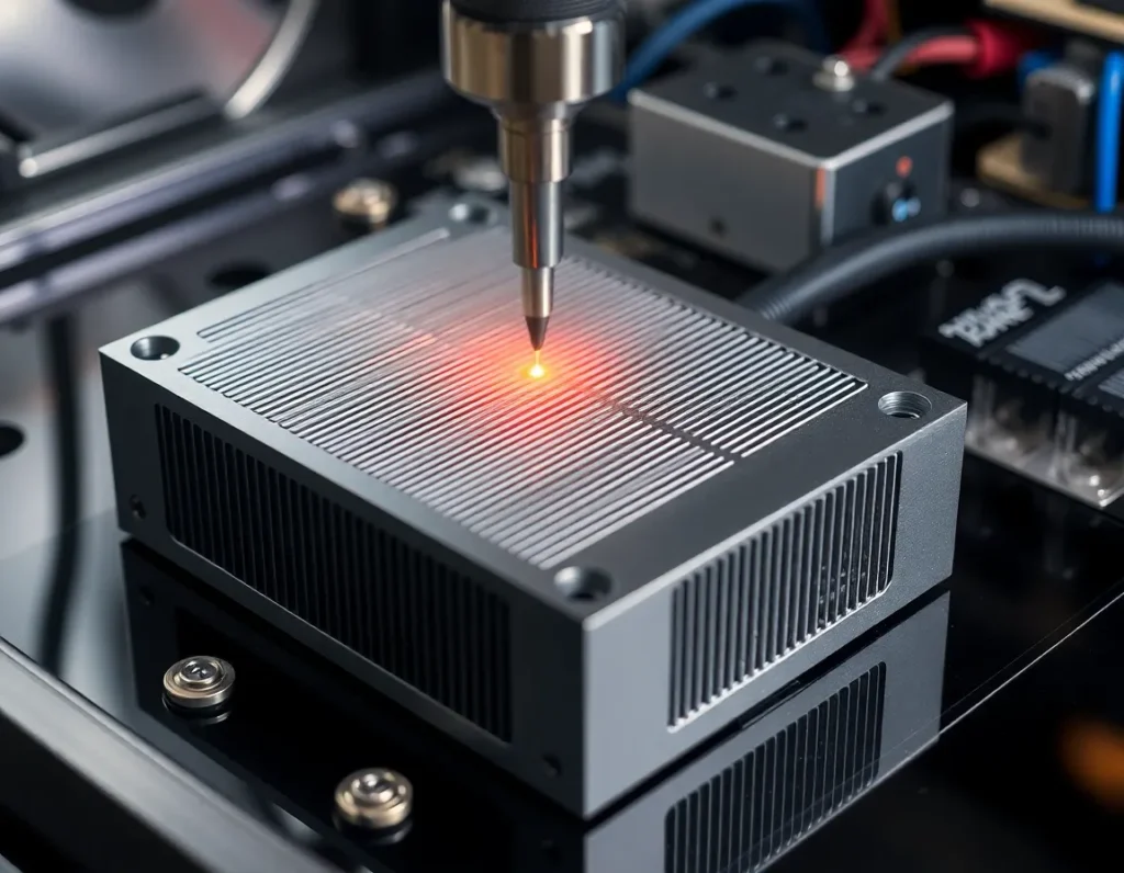
Das CNC-Fräsen ist der Hauptprozess. Ein Metallblock (das “Werkstück”) wird auf einem beweglichen Tisch fixiert, und ein rotierendes mehrschneidiges Schneidwerkzeug entfernt Material. Bei GPU-Blöcken geschieht dies in mehreren Stufen und Achsen. 3-Achsen-Fräsen ist üblich für einfachere Geometrien, aber 5-Achsen-Fräsen wird oft für komplexe Vollabdeckungsblöcke mit integrierten Kanälen und Befestigungspunkten auf mehreren Ebenen eingesetzt. Der Fräsprozess erzeugt die O-Ring-Nuten, Anschlussgewinde, Befestigungsschraubenlöcher, den Hauptkühlmittelhohlraum und die äußeren ästhetischen Merkmale. Der kritischste Fräsvorgang ist die Erstellung des Mikrolamellen-Arrays auf der Kühlplatte. Dies erfordert spezielle Mikrowerkzeuge, oft kleiner als 1 mm im Durchmesser, die sich mit hoher Geschwindigkeit und minimaler Vibration bewegen, um Werkzeugbruch zu verhindern und Maßgenauigkeit zu gewährleisten.
CNC-Bohren
Während beim Fräsen rotierende Schneidwerkzeuge verwendet werden, werden beim Bohren runde Löcher erzeugt. Bei der Blockherstellung wird CNC-Bohren präzise für die Einlass- und Auslassöffnungen eingesetzt, die mit den Kühlmittelschläuchen verbunden werden. Diese Löcher müssen perfekt senkrecht und glatt bearbeitet sein, um eine gute Abdichtung mit den Anschlüssen zu gewährleisten. Tiefbohren kann auch verwendet werden, um interne vertikale Durchgänge in mehrschichtigen Blockdesigns für die Kühlmittelverteilung zu schaffen.
Veredelungsprozesse
Nachdem das primäre Metall entfernt wurde, sind mehrere Veredelungsschritte entscheidend:
- Entgraten: Manual or automated removal of tiny raised edges or “burrs” left by cutting tools, especially critical inside fluid channels to ensure smooth laminar flow.
- Lapping/Sanding: The GPU contact surface is often hand-lapped or machine-sanded on a perfectly flat plate with progressively finer abrasives. This achieves the mirror-flat finish necessary for optimal thermal contact.
- Cleaning: Intensive ultrasonic cleaning in specialized solutions removes all machining oil, metal dust, and abrasive particles from the intricate internal channels. Any residue would contaminate the coolant and degrade performance.
- Surface Plating (if applicable): For blocks using nickel-plated copper, the machined copper component undergoes an electrochemical plating process to apply a layer of nickel for corrosion resistance and aesthetics, before a final cleaning.
This symphony of CNC-controlled and manual finishing processes ensures the block is not just shaped correctly, but is hydraulically smooth, thermally optimal, and impeccably clean.
Material Selection for GPU Cooling Blocks: Copper, Nickel, and Aluminum
The choice of material is a fundamental engineering decision in GPU-Kühlblock-Bearbeitung, directly trading off between thermal performance, corrosion resistance, weight, cost, and manufacturability.
Copper (Cu)
Copper is the undisputed king of thermal performance for cooling blocks. With a thermal conductivity of approximately 385-400 W/(m·K), it transfers heat from the GPU die to the coolant more effectively than any other practical metal. It is also relatively easy to machine, allowing for the creation of sharp, fine micro-fins. Nearly all high-performance blocks use a copper cold plate. Its primary drawbacks are its propensity to oxidize (develop a patina) and its susceptibility to galvanic corrosion if paired with aluminum in the same loop without proper inhibitors. It is also dense and expensive.
Nickel (Ni) – Almost Always a Plating
Pure nickel blocks are exceedingly rare due to cost and machining difficulty. Instead, nickel is used as an electroplated surface layer over a copper substrate. Nickel plating, typically 5-15 microns thick, serves two main purposes: corrosion resistance and aesthetics. It forms a hard, stable barrier that protects the underlying copper from oxidation and galvanic corrosion. It also provides the signature shiny, silver finish favored by many enthusiasts. The plating must be applied evenly and adhere perfectly; any porosity or flaking can expose the copper and lead to localized corrosion. While nickel has lower thermal conductivity (~90 W/(m·K)) than copper, the layer is so thin that its impact on overall thermal resistance is minimal.
Aluminum (Al)
Aluminum, with a thermal conductivity around 160-200 W/(m·K), is a distant second to copper in pure thermal performance. However, it is significantly lighter, cheaper, and easier to mass-produce through casting and machining. Its use is almost exclusively in all-in-one (AIO) liquid coolers and entry-level cooling solutions where cost and weight are primary constraints. A critical rule in liquid cooling is to never mix aluminum and copper components in the same loop without specialized coolant, as the difference in electrochemical potential will cause rapid galvanic corrosion, clogging fins and destroying blocks.
The material selection directly influences the machining strategy. Softer copper allows for more aggressive cuts and finer details but requires care to avoid gouging. Aluminum machines quickly and cleanly but can be gummy, requiring sharp tools and specific feed rates. The chosen material ultimately sets the ceiling for the block’s potential thermal efficiency, which the machining process then strives to fully realize.
Advanced Techniques: Micro-Fin Structures and Jet Impingement Plates
Pushing beyond the foundational milling and drilling of a basic cold plate and channels lies the realm of advanced GPU-Kühlblock-Bearbeitung. Here, the precision of modern CNC technology is leveraged not just to create a path for coolant, but to engineer microscopic turbulence and direct, high-velocity fluid impacts that dramatically enhance heat extraction. Two techniques stand at the forefront of high-performance cooling: micro-fin arrays and jet impingement plates.
Micro-Fin Arrays
Imagine replacing the smooth floor of a coolant channel with a dense forest of microscopic fins. This is the principle behind micro-fin arrays. Using specialized micro-tools, often with diameters between 0.2mm and 0.5mm, CNC machines carve hundreds of these tiny fins directly into the copper or nickel-plated copper cold plate. The purpose is multifaceted. First, they drastically increase the surface area in direct contact with the coolant, providing more “skin” for heat to transfer into the fluid. Second, and more critically, they disrupt laminar flow—the smooth, layered movement of liquid that is poor for heat transfer. The fins force the coolant into a turbulent state, constantly mixing the hotter fluid near the metal with the cooler fluid in the center of the channel. This turbulence ensures the coolant’s thermal capacity is fully utilized before it exits the block. Machining these fins requires exceptionally rigid machines, high spindle speeds, and sophisticated toolpath strategies to prevent tool deflection and breakage, representing a pinnacle of precision manufacturing in cooling solutions.
Jet Impingement
While micro-fins work on creating turbulence across a wide area, jet impingement is a technique of targeted, aggressive cooling. In this design, the cooling block incorporates a secondary plate (the jet plate) positioned between the inlet and the cold plate. This jet plate is machined with an array of precise, small-diameter holes. As pressurized coolant is forced through these holes, it transforms into multiple high-speed jets that shoot directly onto the hottest zones of the cold plate—typically the areas aligned with the GPU die’s cores. This violent impact scrubs away the insulating boundary layer of hotter fluid that naturally clings to the metal surface, achieving some of the highest possible heat transfer coefficients in liquid cooling. The spent fluid then flows sideways into surrounding micro-fin channels for further heat dissipation before exiting. Machining the jet plate requires extreme accuracy in hole diameter, spacing, and alignment to ensure even coverage and optimal pressure distribution across the entire GPU die.
The implementation of these advanced features is a direct response to the concentrated heat flux of modern GPUs. By combining micro-fins for broad-area efficiency with jet impingement for spot-cooling intensity, block manufacturers can design solutions that keep pace with thermal design power (TDP) figures exceeding 500 watts. The transition from simple channels to these engineered structures marks the difference between a cooling block that merely works and one that defines the cutting edge of thermal performance.
Quality Control and Testing: Ensuring Flatness, Leak-Proof Seals, and Thermal Efficiency
The most intricately machined cooling block is a failure if it leaks, doesn’t make proper contact, or performs poorly. Therefore, rigorous quality control and testing protocols are integral to the manufacturing process, acting as the final gatekeeper before a block reaches a customer’s high-end PC.
Dimensional and Surface Flatness Verification
The flatness of the cold plate is non-negotiable. Even a microscopic convex or concave bow can create air gaps between the block and the GPU die, crippling thermal transfer. After machining, blocks undergo precise flatness testing using tools like dial indicators on surface plates or, more commonly, optical flatness scanners. These scanners use light interference patterns to create a topographical map of the surface, measuring deviations down to microns (µm). A typical high-performance block specification demands flatness within 0.05mm or less across the entire IHS contact area. Any block outside this tolerance is re-lapped (precision sanded flat) or scrapped.
Leak Testing Under Pressure
Every single cooling block must be validated as leak-proof. This is not a simple visual check. Blocks are subjected to pressure decay testing. The block’s ports are sealed, and it is pressurized with air or an inert gas to a level significantly higher than normal loop operating pressure (e.g., 1.5 to 2 bar). The system then monitors for any pressure drop over a set period. A drop indicates a leak, often from an imperfect O-ring groove, a micro-crack from machining stress, or a faulty seal in a threaded fitting. Blocks that pass are clean and dry; those that fail are diagnosed and repaired if possible.
Thermal Performance Benchmarking
While dimensional checks ensure the block can be installed, thermal testing proves it works. Manufacturers use standardized test benches to quantify performance. A thermal test head (simulating a GPU die) generates a known, controlled amount of heat. The block is mounted with a standardized thermal paste and torque, and coolant at a set temperature and flow rate is passed through it. Sensors measure the temperature difference between the coolant (∆T) and the heat source. This data is used to calculate thermal resistance (in °C/W)—the ultimate metric of a block’s efficiency. Lower resistance means better performance. This testing validates design choices, machining quality of micro-features, and ensures consistency from batch to batch. It’s the final, definitive proof that the machining and assembly processes have come together to create a product that performs as engineered.
Custom vs. Mass-Produced: Machining for Enthusiasts and OEMs
The world of GPU water blocks splits into two distinct paradigms, each with its own machining philosophy, scale, and economic drivers: mass production for original equipment manufacturers (OEMs) and the custom market for PC enthusiasts.
Mass-Produced OEM Blocks
This domain is defined by scale, cost-efficiency, and reliability for a broad market. Think of the cooling solutions pre-installed on liquid-cooled graphics cards from major brands or standard all-in-one (AIO) coolers. Here, machining is highly optimized for volume. Processes often involve casting the main block body from aluminum (for AIOs) or copper, then using high-speed CNC machining centers in automated production lines to finish critical surfaces, drill ports, and mill channel patterns. Tolerances are tight but focused on repeatability over absolute perfection. The design is usually simplified for manufacturability—wider channels, fewer ultra-fine micro-fins—to maximize yield and minimize machining time. The primary goal is to produce thousands of identical, reliable units at a low cost per unit, meeting a guaranteed performance standard for the OEM’s product.
Custom and Enthusiast-Grade Blocks
At the opposite end of the spectrum lies the custom market, catering to the modding and extreme performance community. Here, the focus shifts from cost to ultimate performance, aesthetics, and compatibility with specific, often rare, graphics card models. Machining is done in smaller batches or even as one-off commissions. Manufacturers like EKWB, Watercool, and Bitspower use full CNC machining from solid copper or brass billets, even for complex shapes, avoiding casting entirely for superior material integrity and detail. This allows for daring designs: intricate, deep micro-fin arrays, integrated RGB light channels, and acrylic tops with elaborate milled logos. Tolerances are obsessive, and finishing processes like meticulous hand-polishing or multi-layer nickel plating are common. The machining runs are slower, the material waste is higher, and the cost reflects it. This sector thrives on innovation, quickly adapting to new GPU releases and pushing the boundaries of what’s possible in GPU-Kühlblock-Bearbeitung for those who view cooling as a centerpiece of their build.
The dichotomy ensures that liquid cooling remains accessible at an entry level while providing a pinnacle to aspire to for enthusiasts. Both sectors rely on precision machining, but they apply its capabilities to solve fundamentally different business and engineering challenges.
Zusammenfassung der wichtigsten Punkte
GPU cooling block machining is a sophisticated discipline that transforms raw metal into a critical thermal management component. It begins with selecting the right material—copper for its unmatched conductivity, often nickel-plated for corrosion resistance, or aluminum for cost-sensitive applications, with careful avoidance of galvanic corrosion. The core processes of CNC milling, drilling, and finishing create the fundamental structure: the cold plate for die contact and the channels for coolant flow.
Advanced techniques elevate performance. Micro-fin arrays, machined with tiny tools, create turbulent flow and massive surface area for efficient heat transfer. Jet impingement plates use precisely drilled holes to blast coolant directly onto hot spots, disrupting the thermal boundary layer for maximum cooling intensity. These features are direct responses to the extreme heat flux of modern graphics processors.
None of this precision matters without rigorous quality control. Every block must pass stringent tests for cold plate flatness (within hundredths of a millimeter), undergo pressurized leak testing, and be thermally benchmarked to verify its performance against a calculated thermal resistance metric. This ensures reliability and efficacy.
Finally, the machining approach diverges based on the market. Mass-produced blocks for OEMs prioritize high-volume, cost-effective manufacturing with reliable performance. In contrast, the custom enthusiast market employs full-CNC machining from solid billets to achieve peak thermal performance, intricate aesthetics, and support for niche hardware, representing the artisanal peak of the craft. Together, these facets of machining make liquid cooling a viable and high-performance solution for GPUs at every level of the computing world.
Häufig gestellte Fragen (FAQ)
What is the single most important factor in GPU block performance?
While material and design are crucial, the quality of the contact between the block’s cold plate and the GPU die is paramount. This is determined by the machining flatness of the plate and the mounting pressure. Even the best copper block with micro-fins will underperform if the surface isn’t perfectly flat, creating insulating air gaps. This is why premium blocks undergo such rigorous flatness verification.
Can I machine my own custom GPU water block?
Technically yes, but it is an exceptionally challenging project requiring advanced machining skills and equipment. You need a capable CNC mill, micro-tools for fin structures, precise CAD/CAM programming, and the ability to perform leak and pressure testing. For most, purchasing a professionally machined block designed for their specific GPU model is far more practical, reliable, and cost-effective.
Why are some blocks made from a single piece of metal (monoblock) for the GPU and VRM, while others are separate?
This is a design and machining choice. A monoblock cools the GPU, VRM (voltage regulation modules), and sometimes memory with one unit, offering a clean aesthetic and simplified loop. However, it is larger, more complex to machine, and specific to one graphics card model. Separate blocks offer modularity and may allow for more focused cooling on the GPU die itself, but require more fittings and tubing. Machining a monoblock involves a more complex, multi-level milling operation to create different channel depths for various components.
How does nickel plating affect performance and machining?
Nickel plating is applied electrochemically after the copper block is machined. It adds a thin, protective layer that prevents copper oxidation (tarnishing) and improves compatibility with coolants and other loop metals. The plating slightly reduces thermal conductivity compared to bare copper, as nickel is less conductive, but the difference in a thin layer is minimal (1-3°C typically). The machining itself is done on the copper substrate, as plating would be destroyed by cutting tools.
Is a block with more, finer coolant channels always better?
Not necessarily. While dense micro-fins increase surface area, they also increase flow restriction (pressure drop). Your pump must be strong enough to overcome this restriction and maintain adequate flow rate through the entire loop. A balance must be struck. A block with extreme fin density might outperform on a test bench with a powerful standalone pump, but could cause overall loop failure in a system with a weaker pump. Good block design optimizes for heat transfer and manageable flow restriction.
How long does it take to machine a single high-end GPU water block?
For a custom, enthusiast-grade block machined from a solid copper billet, the total CNC machining time can range from 45 minutes to over 2 hours per block, depending on the complexity of the fin structure, top design, and logos. This doesn’t include time for plating, polishing, cleaning, assembly, and testing. Mass-produced blocks have cycle times measured in minutes due to optimized toolpaths and often starting from pre-cast near-net shapes.