
서론: GPU 냉각 블록 가공의 정밀 예술
모든 프레임과 메가헤르츠가 중요한 PC 성능의 고부담 세계에서 열과의 싸움은 끊임없이 이어집니다. 이 열전의 중심에는 놀라운 엔지니어링의 결정체인 GPU 냉각 블록이 있습니다. 단순한 금속 덩어리가 아니라, 그 성능이 제작의 엄격한 과학에 의해 좌우되는 정교하게 제작된 마이크로 엔지니어링의 걸작입니다. gpu 냉각 블록 가공 의 과정은 단순한 제조 단계가 아니라, 뜨겁게 타오르는 그래픽 프로세서와 이를 제어하는 냉각 액체 사이의 주요 인터페이스로 원자재를 변환하는 기초적인 예술입니다. 이 정밀 예술은 유체 역학, 열전도율, 기계적 무결성의 균형을 맞추며, 마이크론 단위의 공차를 요구합니다. 구리나 알루미늄의 단단한 블록에서 복잡한 채널과 핀의 미로로 변모하는 여정은 첨단 제조의 증거이며, 절단 품질이 고급 게이밍 리그나 워크스테이션의 조용함, 안정성, 오버클러킹 여유로 직결됩니다.
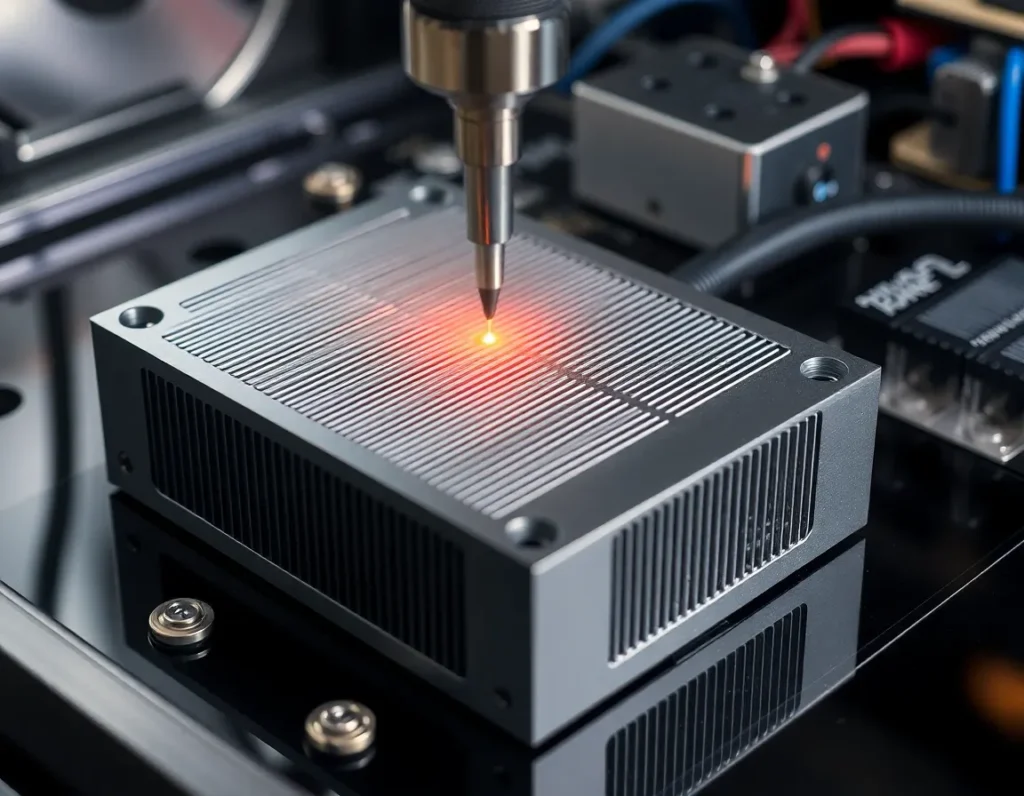
GPU 냉각 블록이란? 구조와 핵심 기능
GPU 냉각 블록은 커스텀 수랭 루프에서 흔히 워터 블록이라고 불리며, 직접 접촉식 열교환기입니다. 핵심 기능은 그래픽 처리 장치(GPU) 다이와 VRAM, VRM 같은 관련 부품에서 발생하는 폐열을 포집하여 흐르는 냉각수로 효율적으로 전달하는 것입니다. 부피가 큰 공랭 쿨러와 달리, 금속 대 금속의 긴밀한 접촉과 최적화된 액체 유로를 통해 이를 달성합니다.
구조적으로, 일반적인 풀커버 GPU 블록은 다음과 같은 몇 가지 핵심 층으로 구성됩니다:
- 콜드 플레이트: 이것은 블록의 심장부입니다. GPU 칩 위에 직접 놓이는 평평한 가공 금속 판입니다. 그 밑면에는 냉각수로의 열 전달을 위한 방대한 표면적을 만들어내는 정밀 가공된 마이크로 핀, 핀, 또는 채널 배열이 있습니다.
- 제트 임핑지먼트 또는 분배 플레이트: 종종 콜드 플레이트 설계에 통합되거나 별도의 층으로 존재하는 이 부품은 냉각수 흐름을 관리합니다. 일련의 입구와 마이크로 노즐을 사용하여 냉각수를 콜드 플레이트의 가장 뜨거운 영역으로 강제로 유도하여 경계층을 깨고 열 교환을 극대화합니다.
- 메인 하우징 또는 상판: 이 구조 부품은 냉각 챔버를 밀봉합니다. 냉각수 튜브용 입구와 출구 포트를 포함하며, 종종 아크릴 창이나 복잡한 CNC 밀링 디자인과 같은 미적 요소를 갖춥니다. 변형 없이 클램핑 압력과 내부 유체 압력을 견딜 수 있을 만큼 견고해야 합니다.
- 장착 하드웨어 및 열 인터페이스: 나사, 백플레이트, 스탠드오프로 구성된 시스템이 균일하고 안정적인 장착 압력을 보장합니다. 콜드 플레이트와 GPU 다이 사이에는 고성능 서멀 페이스트 또는 패드를 도포하여 미세한 요철을 메우고 최적의 열 전도를 보장합니다.
본질적으로 이 블록은 밀폐된 가압 마이크로 채널 시스템으로, 냉각수가 가능한 한 빠르게 열을 흡수한 후 라디에이터로 이동하도록 강제됩니다. 이 전체 시스템의 효율성은 가공 공정에서 탄생합니다.
액체 냉각 성능에서 가공이 차지하는 결정적 역할
평균적인 액체 냉각 솔루션과 탁월한 액체 냉각 솔루션 사이의 성능 격차는 거의 전적으로 가공 과정에서 형성됩니다. 이 단계는 열적 및 유체적 성능을 좌우하는 근본적인 물리적 특성을 결정합니다. 가공에 의존하는 세 가지 핵심 요소는 표면 평탄도, 채널 형상, 그리고 밀봉 무결성입니다.
첫째, 콜드 플레이트 접촉면의 평탄도는 타협할 수 없습니다. GPU 다이는 일반적으로 면적이 수백 제곱밀리미터에 불과합니다. 콜드 플레이트의 미세한 휨이나 불균일은 공기층을 만들어내며, 이는 최악의 열 절연체입니다. 고정밀 가공과 이어지는 래핑 공정은 거의 완벽하게 평평한 표면을 보장하여, 열 인터페이스 소재가 방해 없이 열을 전달할 수 있도록 얇고 일정한 층을 형성하게 합니다.
둘째, 내부 냉각 구조—핀, 기둥, 채널—의 형상은 가공 능력의 직접적인 산물입니다. 이러한 특징들의 밀도, 높이, 두께는 블록의 열 성능과 유동 저항을 결정합니다. 더 미세하고 촘촘한 마이크로 핀은 열 교환을 위한 더 많은 표면적을 제공하지만 냉각수 흐름을 제한하여 더 높은 펌프 압력을 필요로 합니다. 가공 공정은 이러한 섬세한 형상들을 날카롭고 깨끗한 모서리와 일정한 치수로 깎아내야 합니다. 버(burr)나 편차는 유동 사점(dead spot)을 만들고, 압력 강하를 증가시키며, 기포를 가두어 효율을 심각하게 저해할 수 있습니다.
마지막으로, 가공은 밀봉 표면을 정의합니다. 콜드 플레이트, O-링 홈, 상판 사이의 접합면은 완벽하게 매끄럽고 평행해야 합니다. 여기의 어떤 결함도 누수로 이어질 수 있으며, 이는 PC에서 치명적입니다. O-링 채널의 깊이와 폭의 정밀도는 실리콘 씰이 올바르게 압축되어 고압 냉각수에 대한 신뢰할 수 있고 오래 지속되는 장벽을 형성하도록 보장합니다. 요컨대, 가공은 이론적 설계를 열 전도, 유체 역학, 기계적 신뢰성에서 동시에 뛰어난 물리적 실체로 변환합니다.
주요 가공 공정: CNC 밀링, 드릴링 및 마감
GPU 냉각 블록의 제작은 컴퓨터 수치 제어(CNC) 가공이 주를 이루며, 이는 사전 프로그래밍된 소프트웨어가 공장 공구와 기계의 움직임을 지시하는 절삭 가공 공정입니다. 이를 통해 요구되는 극한의 정밀도와 반복성을 얻을 수 있습니다.
CNC 밀링
CNC 밀링은 주력 공정입니다. 금속 블록(“공작물”)이 이동식 베드에 고정되고, 회전하는 다점 절삭 공구가 재료를 제거합니다. GPU 블록의 경우 이는 여러 단계와 축에서 이루어집니다. 3축 밀링은 단순한 형상에 일반적이지만, 통합 채널과 여러 평면의 장착 지점을 가진 복잡한 풀커버 블록에는 종종 5축 밀링이 사용됩니다. 밀링 공정은 O-링 홈, 포트 나사산, 장착 나사 구멍, 메인 냉각수 캐비티, 외부 미관 특징을 생성합니다. 가장 중요한 밀링 작업은 콜드 플레이트에 마이크로 핀 어레이를 생성하는 것입니다. 이를 위해서는 직경이 종종 1mm보다 작은 특수 마이크로 공구가 필요하며, 공구 파손을 방지하고 치수 정확도를 보장하기 위해 최소한의 진동으로 고속으로 움직여야 합니다.
CNC 드릴링
밀링이 회전 절삭기를 사용하는 반면, 드릴링은 둥근 구멍을 만듭니다. 블록 제조에서 CNC 드릴링은 냉각수 튜브에 연결되는 입구 및 출구 포트에 정밀하게 사용됩니다. 이 구멍들은 완벽하게 수직이고 매끄럽게 마감되어 피팅과의 좋은 밀봉을 보장해야 합니다. 깊은 구멍 드릴링은 냉각수 분배를 위한 다층 블록 설계에서 내부 수직 통로를 만드는 데에도 사용될 수 있습니다.
마감 공정
주요 금속 제거 후, 몇 가지 마감 단계가 중요합니다:
- 디버링: Manual or automated removal of tiny raised edges or “burrs” left by cutting tools, especially critical inside fluid channels to ensure smooth laminar flow.
- Lapping/Sanding: The GPU contact surface is often hand-lapped or machine-sanded on a perfectly flat plate with progressively finer abrasives. This achieves the mirror-flat finish necessary for optimal thermal contact.
- Cleaning: Intensive ultrasonic cleaning in specialized solutions removes all machining oil, metal dust, and abrasive particles from the intricate internal channels. Any residue would contaminate the coolant and degrade performance.
- Surface Plating (if applicable): For blocks using nickel-plated copper, the machined copper component undergoes an electrochemical plating process to apply a layer of nickel for corrosion resistance and aesthetics, before a final cleaning.
This symphony of CNC-controlled and manual finishing processes ensures the block is not just shaped correctly, but is hydraulically smooth, thermally optimal, and impeccably clean.
Material Selection for GPU Cooling Blocks: Copper, Nickel, and Aluminum
The choice of material is a fundamental engineering decision in gpu 냉각 블록 가공, directly trading off between thermal performance, corrosion resistance, weight, cost, and manufacturability.
Copper (Cu)
Copper is the undisputed king of thermal performance for cooling blocks. With a thermal conductivity of approximately 385-400 W/(m·K), it transfers heat from the GPU die to the coolant more effectively than any other practical metal. It is also relatively easy to machine, allowing for the creation of sharp, fine micro-fins. Nearly all high-performance blocks use a copper cold plate. Its primary drawbacks are its propensity to oxidize (develop a patina) and its susceptibility to galvanic corrosion if paired with aluminum in the same loop without proper inhibitors. It is also dense and expensive.
Nickel (Ni) – Almost Always a Plating
Pure nickel blocks are exceedingly rare due to cost and machining difficulty. Instead, nickel is used as an electroplated surface layer over a copper substrate. Nickel plating, typically 5-15 microns thick, serves two main purposes: corrosion resistance and aesthetics. It forms a hard, stable barrier that protects the underlying copper from oxidation and galvanic corrosion. It also provides the signature shiny, silver finish favored by many enthusiasts. The plating must be applied evenly and adhere perfectly; any porosity or flaking can expose the copper and lead to localized corrosion. While nickel has lower thermal conductivity (~90 W/(m·K)) than copper, the layer is so thin that its impact on overall thermal resistance is minimal.
Aluminum (Al)
Aluminum, with a thermal conductivity around 160-200 W/(m·K), is a distant second to copper in pure thermal performance. However, it is significantly lighter, cheaper, and easier to mass-produce through casting and machining. Its use is almost exclusively in all-in-one (AIO) liquid coolers and entry-level cooling solutions where cost and weight are primary constraints. A critical rule in liquid cooling is to never mix aluminum and copper components in the same loop without specialized coolant, as the difference in electrochemical potential will cause rapid galvanic corrosion, clogging fins and destroying blocks.
The material selection directly influences the machining strategy. Softer copper allows for more aggressive cuts and finer details but requires care to avoid gouging. Aluminum machines quickly and cleanly but can be gummy, requiring sharp tools and specific feed rates. The chosen material ultimately sets the ceiling for the block’s potential thermal efficiency, which the machining process then strives to fully realize.
Advanced Techniques: Micro-Fin Structures and Jet Impingement Plates
Pushing beyond the foundational milling and drilling of a basic cold plate and channels lies the realm of advanced gpu 냉각 블록 가공. Here, the precision of modern CNC technology is leveraged not just to create a path for coolant, but to engineer microscopic turbulence and direct, high-velocity fluid impacts that dramatically enhance heat extraction. Two techniques stand at the forefront of high-performance cooling: micro-fin arrays and jet impingement plates.
Micro-Fin Arrays
Imagine replacing the smooth floor of a coolant channel with a dense forest of microscopic fins. This is the principle behind micro-fin arrays. Using specialized micro-tools, often with diameters between 0.2mm and 0.5mm, CNC machines carve hundreds of these tiny fins directly into the copper or nickel-plated copper cold plate. The purpose is multifaceted. First, they drastically increase the surface area in direct contact with the coolant, providing more “skin” for heat to transfer into the fluid. Second, and more critically, they disrupt laminar flow—the smooth, layered movement of liquid that is poor for heat transfer. The fins force the coolant into a turbulent state, constantly mixing the hotter fluid near the metal with the cooler fluid in the center of the channel. This turbulence ensures the coolant’s thermal capacity is fully utilized before it exits the block. Machining these fins requires exceptionally rigid machines, high spindle speeds, and sophisticated toolpath strategies to prevent tool deflection and breakage, representing a pinnacle of precision manufacturing in cooling solutions.
Jet Impingement
While micro-fins work on creating turbulence across a wide area, jet impingement is a technique of targeted, aggressive cooling. In this design, the cooling block incorporates a secondary plate (the jet plate) positioned between the inlet and the cold plate. This jet plate is machined with an array of precise, small-diameter holes. As pressurized coolant is forced through these holes, it transforms into multiple high-speed jets that shoot directly onto the hottest zones of the cold plate—typically the areas aligned with the GPU die’s cores. This violent impact scrubs away the insulating boundary layer of hotter fluid that naturally clings to the metal surface, achieving some of the highest possible heat transfer coefficients in liquid cooling. The spent fluid then flows sideways into surrounding micro-fin channels for further heat dissipation before exiting. Machining the jet plate requires extreme accuracy in hole diameter, spacing, and alignment to ensure even coverage and optimal pressure distribution across the entire GPU die.
The implementation of these advanced features is a direct response to the concentrated heat flux of modern GPUs. By combining micro-fins for broad-area efficiency with jet impingement for spot-cooling intensity, block manufacturers can design solutions that keep pace with thermal design power (TDP) figures exceeding 500 watts. The transition from simple channels to these engineered structures marks the difference between a cooling block that merely works and one that defines the cutting edge of thermal performance.
Quality Control and Testing: Ensuring Flatness, Leak-Proof Seals, and Thermal Efficiency
The most intricately machined cooling block is a failure if it leaks, doesn’t make proper contact, or performs poorly. Therefore, rigorous quality control and testing protocols are integral to the manufacturing process, acting as the final gatekeeper before a block reaches a customer’s high-end PC.
Dimensional and Surface Flatness Verification
The flatness of the cold plate is non-negotiable. Even a microscopic convex or concave bow can create air gaps between the block and the GPU die, crippling thermal transfer. After machining, blocks undergo precise flatness testing using tools like dial indicators on surface plates or, more commonly, optical flatness scanners. These scanners use light interference patterns to create a topographical map of the surface, measuring deviations down to microns (µm). A typical high-performance block specification demands flatness within 0.05mm or less across the entire IHS contact area. Any block outside this tolerance is re-lapped (precision sanded flat) or scrapped.
Leak Testing Under Pressure
Every single cooling block must be validated as leak-proof. This is not a simple visual check. Blocks are subjected to pressure decay testing. The block’s ports are sealed, and it is pressurized with air or an inert gas to a level significantly higher than normal loop operating pressure (e.g., 1.5 to 2 bar). The system then monitors for any pressure drop over a set period. A drop indicates a leak, often from an imperfect O-ring groove, a micro-crack from machining stress, or a faulty seal in a threaded fitting. Blocks that pass are clean and dry; those that fail are diagnosed and repaired if possible.
Thermal Performance Benchmarking
While dimensional checks ensure the block can be installed, thermal testing proves it works. Manufacturers use standardized test benches to quantify performance. A thermal test head (simulating a GPU die) generates a known, controlled amount of heat. The block is mounted with a standardized thermal paste and torque, and coolant at a set temperature and flow rate is passed through it. Sensors measure the temperature difference between the coolant (∆T) and the heat source. This data is used to calculate thermal resistance (in °C/W)—the ultimate metric of a block’s efficiency. Lower resistance means better performance. This testing validates design choices, machining quality of micro-features, and ensures consistency from batch to batch. It’s the final, definitive proof that the machining and assembly processes have come together to create a product that performs as engineered.
Custom vs. Mass-Produced: Machining for Enthusiasts and OEMs
The world of GPU water blocks splits into two distinct paradigms, each with its own machining philosophy, scale, and economic drivers: mass production for original equipment manufacturers (OEMs) and the custom market for PC enthusiasts.
Mass-Produced OEM Blocks
This domain is defined by scale, cost-efficiency, and reliability for a broad market. Think of the cooling solutions pre-installed on liquid-cooled graphics cards from major brands or standard all-in-one (AIO) coolers. Here, machining is highly optimized for volume. Processes often involve casting the main block body from aluminum (for AIOs) or copper, then using high-speed CNC machining centers in automated production lines to finish critical surfaces, drill ports, and mill channel patterns. Tolerances are tight but focused on repeatability over absolute perfection. The design is usually simplified for manufacturability—wider channels, fewer ultra-fine micro-fins—to maximize yield and minimize machining time. The primary goal is to produce thousands of identical, reliable units at a low cost per unit, meeting a guaranteed performance standard for the OEM’s product.
Custom and Enthusiast-Grade Blocks
At the opposite end of the spectrum lies the custom market, catering to the modding and extreme performance community. Here, the focus shifts from cost to ultimate performance, aesthetics, and compatibility with specific, often rare, graphics card models. Machining is done in smaller batches or even as one-off commissions. Manufacturers like EKWB, Watercool, and Bitspower use full CNC machining from solid copper or brass billets, even for complex shapes, avoiding casting entirely for superior material integrity and detail. This allows for daring designs: intricate, deep micro-fin arrays, integrated RGB light channels, and acrylic tops with elaborate milled logos. Tolerances are obsessive, and finishing processes like meticulous hand-polishing or multi-layer nickel plating are common. The machining runs are slower, the material waste is higher, and the cost reflects it. This sector thrives on innovation, quickly adapting to new GPU releases and pushing the boundaries of what’s possible in gpu 냉각 블록 가공 for those who view cooling as a centerpiece of their build.
The dichotomy ensures that liquid cooling remains accessible at an entry level while providing a pinnacle to aspire to for enthusiasts. Both sectors rely on precision machining, but they apply its capabilities to solve fundamentally different business and engineering challenges.
핵심 요점 요약
GPU cooling block machining is a sophisticated discipline that transforms raw metal into a critical thermal management component. It begins with selecting the right material—copper for its unmatched conductivity, often nickel-plated for corrosion resistance, or aluminum for cost-sensitive applications, with careful avoidance of galvanic corrosion. The core processes of CNC milling, drilling, and finishing create the fundamental structure: the cold plate for die contact and the channels for coolant flow.
Advanced techniques elevate performance. Micro-fin arrays, machined with tiny tools, create turbulent flow and massive surface area for efficient heat transfer. Jet impingement plates use precisely drilled holes to blast coolant directly onto hot spots, disrupting the thermal boundary layer for maximum cooling intensity. These features are direct responses to the extreme heat flux of modern graphics processors.
None of this precision matters without rigorous quality control. Every block must pass stringent tests for cold plate flatness (within hundredths of a millimeter), undergo pressurized leak testing, and be thermally benchmarked to verify its performance against a calculated thermal resistance metric. This ensures reliability and efficacy.
Finally, the machining approach diverges based on the market. Mass-produced blocks for OEMs prioritize high-volume, cost-effective manufacturing with reliable performance. In contrast, the custom enthusiast market employs full-CNC machining from solid billets to achieve peak thermal performance, intricate aesthetics, and support for niche hardware, representing the artisanal peak of the craft. Together, these facets of machining make liquid cooling a viable and high-performance solution for GPUs at every level of the computing world.
Frequently Asked Questions (FAQ)
What is the single most important factor in GPU block performance?
While material and design are crucial, the quality of the contact between the block’s cold plate and the GPU die is paramount. This is determined by the machining flatness of the plate and the mounting pressure. Even the best copper block with micro-fins will underperform if the surface isn’t perfectly flat, creating insulating air gaps. This is why premium blocks undergo such rigorous flatness verification.
Can I machine my own custom GPU water block?
Technically yes, but it is an exceptionally challenging project requiring advanced machining skills and equipment. You need a capable CNC mill, micro-tools for fin structures, precise CAD/CAM programming, and the ability to perform leak and pressure testing. For most, purchasing a professionally machined block designed for their specific GPU model is far more practical, reliable, and cost-effective.
Why are some blocks made from a single piece of metal (monoblock) for the GPU and VRM, while others are separate?
This is a design and machining choice. A monoblock cools the GPU, VRM (voltage regulation modules), and sometimes memory with one unit, offering a clean aesthetic and simplified loop. However, it is larger, more complex to machine, and specific to one graphics card model. Separate blocks offer modularity and may allow for more focused cooling on the GPU die itself, but require more fittings and tubing. Machining a monoblock involves a more complex, multi-level milling operation to create different channel depths for various components.
How does nickel plating affect performance and machining?
Nickel plating is applied electrochemically after the copper block is machined. It adds a thin, protective layer that prevents copper oxidation (tarnishing) and improves compatibility with coolants and other loop metals. The plating slightly reduces thermal conductivity compared to bare copper, as nickel is less conductive, but the difference in a thin layer is minimal (1-3°C typically). The machining itself is done on the copper substrate, as plating would be destroyed by cutting tools.
Is a block with more, finer coolant channels always better?
Not necessarily. While dense micro-fins increase surface area, they also increase flow restriction (pressure drop). Your pump must be strong enough to overcome this restriction and maintain adequate flow rate through the entire loop. A balance must be struck. A block with extreme fin density might outperform on a test bench with a powerful standalone pump, but could cause overall loop failure in a system with a weaker pump. Good block design optimizes for heat transfer and manageable flow restriction.
How long does it take to machine a single high-end GPU water block?
For a custom, enthusiast-grade block machined from a solid copper billet, the total CNC machining time can range from 45 minutes to over 2 hours per block, depending on the complexity of the fin structure, top design, and logos. This doesn’t include time for plating, polishing, cleaning, assembly, and testing. Mass-produced blocks have cycle times measured in minutes due to optimized toolpaths and often starting from pre-cast near-net shapes.