
Für viele Wellen, Arme, Joche, Naben und Hochlastverbinder ist der tatsächliche Fertigungsweg ein geschmiedetes Rohteil plus CNC-Endbearbeitung. Dieser Leitfaden beginnt bei der mechanischen Beanspruchung und arbeitet sich dann rückwärts zu Halbzeugform, Werkzeugen, Bearbeitungszugabe, Bezugsstrategie, Wärmebehandlung und Prüfung vor.
Ersetzen Sie “Was ist stärker?” durch “Was muss überleben?”
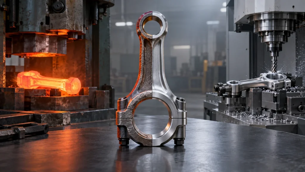 Stärke ist keine einzelne Eigenschaft. Streckgrenze, Zugfestigkeit, Ermüdung, Schlagzähigkeit, Bruchzähigkeit, Härte, Verschleiß und Hochtemperaturverhalten beantworten unterschiedliche Fragen. Geometrie, Oberflächenzustand, Kerben, Eigenspannungen, Wärmebehandlung und Belastungsrichtung können ebenso wichtig sein wie nominelle Materialwerte.
Ein geschmiedeter Vorformling kann den Faserverlauf um eine Form herum ausrichten und Störungen in hochbelasteten Bereichen reduzieren. Ein zerspantes Bauteil aus geeignetem Halbzeug kann ebenfalls sehr gut funktionieren, insbesondere wenn sein Lastpfad einfach ist und der Halbzeugzustand geeignet ist. Die Zerspanung aus dem Vollen gibt Konstrukteuren außerdem die Flexibilität, die Geometrie ohne neue Umformwerkzeuge zu ändern.
Definieren Sie den Versagensmodus, bevor Sie den Weg wählen. Wenn eine Verbindung wiederholter Biegung ausgesetzt ist, eine rotierende Welle Torsion erfährt oder ein Arm Schlagbelastung erhält, sollten Richtung und Konzentration der Spannung die Material- und Prozessentscheidung prägen.
Lassen Sie den Lastpfad den Fertigungsplan führen
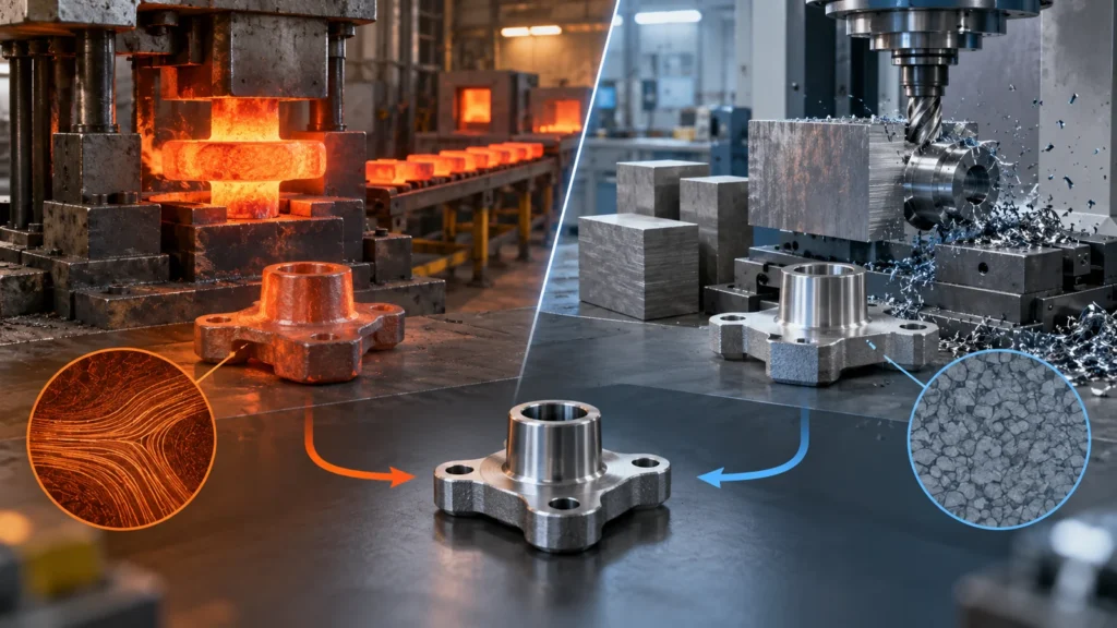 Markieren Sie, wo Kraft eintritt, wie sie verläuft und wo sie austritt. Identifizieren Sie Querschnittsänderungen, Verrundungen, Verzahnungen, Bohrungen, Absätze, Gewinde und Kontaktflächen entlang dieses Pfads. Merkmale, die den Kraftfluss unterbrechen oder Spannungskonzentrationen erzeugen, verdienen besondere Aufmerksamkeit, unabhängig davon, ob das Teil geschmiedet oder spanend bearbeitet wird.
Schmieden kann Material effizient entlang des Pfads platzieren und eine endkonturnahe Hülle mit günstigem Kraftfluss erzeugen. Es bringt jedoch auch Einschränkungen mit sich: Entformungsschräge, Grat, Trennebene, Formfüllung, Querschnittsübergänge, Werkzeugzugänglichkeit und Umformfolge. Spanende Bearbeitung kann präzise Details und glatte, kontrollierte Radien erzeugen, aber ein Schnitt quer zur vorhandenen Faserorientierung des Halbzeugs kann eine geschmiedete Kontur möglicherweise nicht reproduzieren.
Finite-Elemente-Ergebnisse sind nur so nützlich wie ihre Eingaben. Das Modell sollte Eigenschaften verwenden, die den tatsächlichen Halbzeug- oder Schmiedezustand, die Wärmebehandlung, den Oberflächenzustand und das Lastkollektiv repräsentieren. Die Fertigungswahl sollte Teil der Designverifikation sein und nicht erst nach Abschluss des Spannungsberichts hinzugefügt werden.
Knüppel und geschmiedetes Halbzeug sind keine Gegensätze
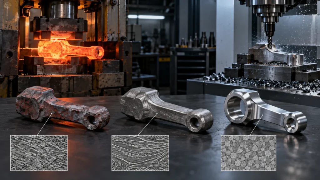 CNC-Maschinen zerspanen jede kontrollierte Ausgangsform, die die Fertigungsroute auswählt. Das kann gewalztes Blech, stranggepresster Stab, Rohr, Gussteil oder Schmiedeteil sein. Daher vergleicht “Schmieden versus CNC” oft ein primäres Umformverfahren mit einem Finish-Verfahren statt sich gegenseitig ausschließende Alternativen.
Die spanende Bearbeitung eines einfachen Prototyps aus Knüppel kann die Geometrie schnell validieren. In der Serienfertigung kann später auf ein Gesenkschmieden umgestellt werden, das Material für die Finish-Bearbeitung stehen lässt. Einige Programme bearbeiten weiterhin aus Halbzeug, weil Bedarf, Änderungen oder Geometrie die Umformwerkzeuge nicht rechtfertigen. Andere verwenden ein Freiform- oder Standard-Schmiedeteil ohne dediziertes endkonturnahes Gesenk.
Geben Sie Materialnorm, Güte, Halbzeug- oder Schmiedezustand, Wärmebehandlung und Zertifizierungsanforderungen an. Die CNC-Bearbeitungsmaterialien Auswahl sollte mit der tatsächlichen Lieferkette verbunden sein und nicht nur mit dem Legierungsnamen.
Geometrie und Volumen bestimmen die Route gemeinsam
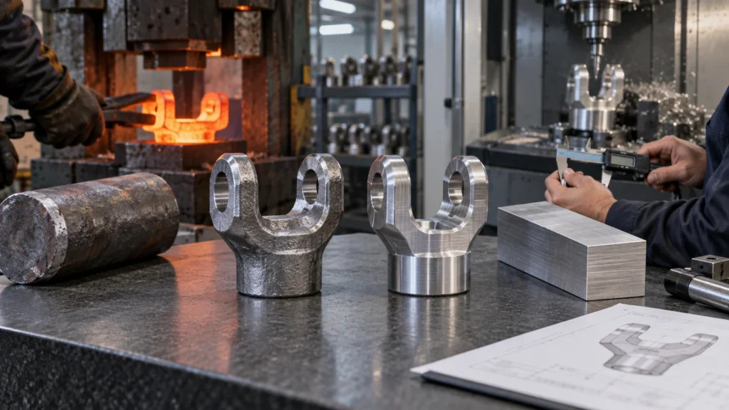
There is no dependable quantity threshold without the part. Tooling complexity, forging size, press availability, alloy, heat treatment, machining reduction, and forecast confidence matter. A high-volume part with little material removal may remain practical from stock; a moderate-volume expensive alloy shape may benefit from a preform sooner.
Planning a Forged-and-Machined Component
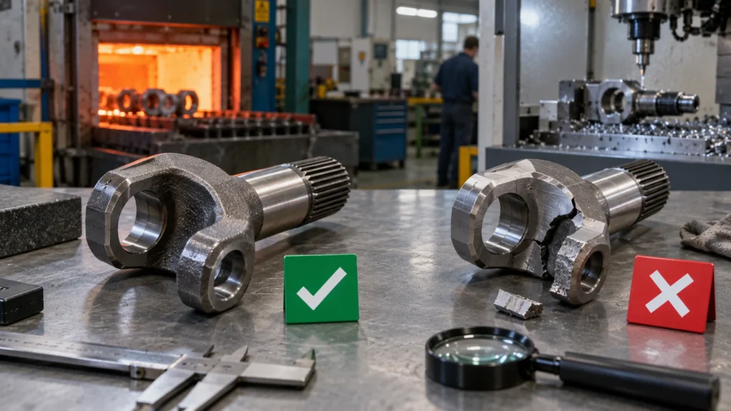 The forging drawing and finished-part drawing must work together. Define the forged envelope, parting and flash regions, draft, trim, scale removal, straightening if needed, and machining allowance. Provide robust locating pads or surfaces for the first operation. Allowance must cover forging variation while avoiding unnecessary cutting.
Datum strategy begins before the first finish cut. Initial workholding locates on a near-net shape; subsequent operations should transition to machined datums. If the forging twists or bows, the setup must distribute stock so all critical features clean up. Simulation and nominal CAD alone cannot replace physical allowance and locating review.
Protect grain flow where it matters. A forging advantage can be weakened if deep machining removes the beneficial outer flow or places critical surfaces in an unfavorable region. The forge and machine suppliers should agree on section cuts and material removal rather than optimizing their operations independently.
Flash trim and parting-line condition also affect machining. A parting mismatch or trim variation can interfere with clamping, consume allowance, or change how the first operation seats. The forging specification should identify areas that may contact fixtures and keep uncontrolled flash away from functional locating surfaces.
Handling protection begins at the rough-blank stage. Dents, scale, aggressive grinding, or mixed identification may later fall within a critical machined region. Mark high-risk surfaces and preserve lot identity before value is added through heat treatment and CNC work.
Heat Treatment Changes the Sequence
Heat treatment can occur before, between, or after machining stages depending on alloy, hardness, distortion risk, surface requirements, and final properties. Rough machining before heat treatment may remove bulk stock and leave allowance for distortion correction. Finishing after treatment may require different tools and parameters. Some features may need protection from decarburization, scale, or surface damage.
Sequence decisions affect datums and inspection. A bore finished before heat treatment may move; a thin wall may distort after stress release; grinding may be required after hardening. Define which dimensions are final at each state. Do not place final drawing limits on an intermediate operation without explaining their purpose.
Material traceability should connect forging lot, heat treatment batch, machining lot, and final inspection. This is particularly important where mechanical test results or special-process records form part of acceptance.
Evidence for High-Load Parts Goes Beyond Dimensions
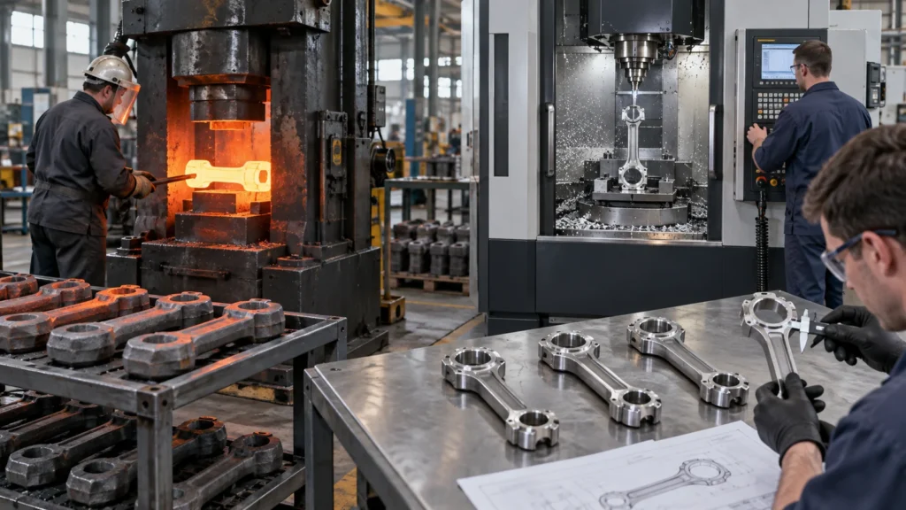 Dimensional inspection proves geometry, not internal quality or material condition. Depending on risk, the plan may include material certificates, heat-treatment records, hardness, mechanical tests, grain-flow studies, magnetic-particle or ultrasonic examination, surface integrity checks, and traceability. The applicable standard and acceptance criteria must be identified by the customer or engineering authority.
For machined-from-stock parts, verify stock orientation and certification where direction matters. For forgings, define sampling and examination regions. For both, protect high-stress surfaces from tool marks, burns, dents, or aggressive blending that could reduce fatigue performance.
The quality package should match consequence. Over-testing a benign bracket wastes cost; under-defining a rotating or safety-related part transfers risk downstream. The site’s quality capability overview can support supplier evaluation, but project-specific requirements still belong on the controlled documents.
First-article approval should include more than one ideal sample when process variation matters. Review parts across cavities, die positions, heats, or production conditions as applicable. The objective is to understand the route’s normal variation before final machining fixtures and gauges are locked around a single favorable blank.
Supplier changes require controlled revalidation. A different forge source, heat-treatment route, stock orientation, or machining setup can alter evidence that was previously accepted. Define which changes require notification and which tests or records must be repeated.
Four Decision Cases
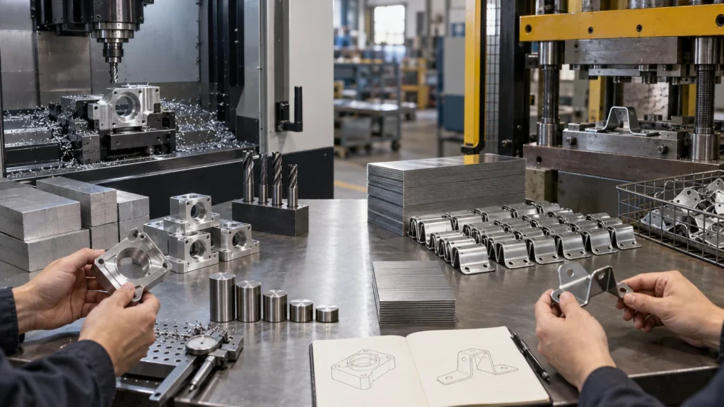
Machine from stock while pivot locations and clearances are changing. Use the prototype to confirm geometry, then reassess whether production loads and volume justify a forged blank.
High-duty yoke
A forged preform may align material around the arms and reduce stock removal. Finish-machine bores, faces, and threads from a datum plan tied to the near-net shape.
Precision housing
If performance is governed by dimensional interfaces rather than directional loading, billet machining may be simpler even at repeat quantities. Do not select forging merely for a generic strength claim.
Replacement shaft with uncertain demand
Machining from certified bar can avoid dedicated dies and inventory. A standard forged stock form may still be used if it meets the specification and supply need.
Beschaffungs-FAQs
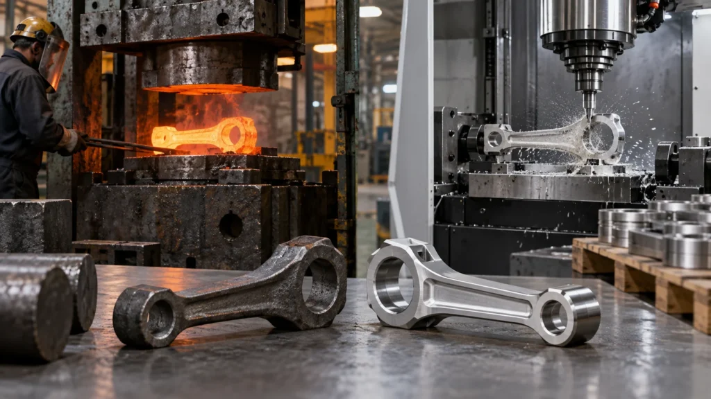
Machining removes material and can intersect the flow pattern of the starting stock or forging. Whether that matters depends on removal depth, flow direction, geometry, and loading. Review highly stressed regions with the material and forging specialists.
Can a forged part meet final tolerances without CNC?
Some noncritical features may remain as forged, but bores, fits, threads, sealing faces, and precise datums commonly need machining or grinding. Allocate requirements by feature.
When is billet best for production?
Billet can remain appropriate when design changes continue, quantities do not justify dies, geometry is machining-friendly, stock is readily available, or performance does not require a near-net forged flow pattern.
Who should own the allowance model?
It should be jointly agreed by forging and machining stakeholders, with clear design authority. The model must satisfy forging feasibility, cleanup, workholding, final geometry, and inspection needs.
These conditions explain why the Vor- und Nachteile der CNC-Bearbeitung should always be evaluated against the complete manufacturing route.