
GD&T-Zeichnungsanforderungen für die CNC-Bearbeitung sind nicht nur eine Liste von Symbolen. Sie sind die Verbindung zwischen dem, was ein Teil leisten muss, wie es während der Bearbeitung positioniert wird und wie das fertige Ergebnis verifiziert wird. Eine Zeichnung kann jedes Nennmaß zeigen und dennoch einen Lieferanten über Bezüge, kritische Merkmale, Prüfverfahren oder den Zustand nach der Oberflächenbehandlung im Unklaren lassen. Eine angebotsreife Zeichnung macht diese Entscheidungen sichtbar, ohne einen unnötig teuren Prozess vorzuschreiben.
Beginnen Sie mit der funktionalen Absicht des Teils

Bevor Sie einen Merkmalskontrollrahmen hinzufügen, identifizieren Sie die Konsequenz der Abweichung. Ein Lochbild kann eine Positionskontrolle erfordern, weil ein Passstift in jedes Loch eintreten muss. Eine Fläche kann eine Rechtwinkligkeit erfordern, weil sie ein Lager trägt. Ein Profil kann wichtig sein, weil eine Dichtung einer konturierten Oberfläche folgt. Wenn die Zeichnung den Fehlermodus nicht erkennen lässt, kann ein Lieferant Aufwand für die Kontrolle des falschen Merkmals aufwenden.
Schlüsselprinzip: Eine GD&T-Angabe ist nützlich, wenn sie beschreibt, wie das Merkmal in der Baugruppe funktionieren muss und wie diese Anforderung bei der Prüfung reproduziert werden kann.
- Positionierende Merkmale: Position und Bezugsbeziehungen priorisieren.
- Rotierende Schnittstellen: Größe, Orientierung, Rundlauf und Oberflächenzustand gemeinsam prüfen.
- Dichtflächen: Ebenheit, Textur, Grate und den endgültigen Beschichtungszustand berücksichtigen.
- Lasttragende Flächen: Form und Orientierung relativ zum tatsächlichen Lastpfad prüfen.
Für die übergreifende Beziehung zwischen funktionalen Grenzen, Prozessstabilität und Prüfung siehe die Website von Leitfaden für CNC-Bearbeitungstoleranzen. Dieser Artikel beschränkt die Diskussion auf die Informationen, die ein Lieferant aus einer kontrollierten Zeichnung benötigt.
Erstellen Sie ein vollständiges Zeichnungspaket

| Paketelement | Was es klären sollte | Häufige Folge, wenn es fehlt |
|---|---|---|
| Kontrollierte Zeichnung | Einheiten, Standardtoleranzen, Bezüge, GD&T, Gewinde, Kanten und Revision | Unterschiedliche Interpretationen desselben Modells |
| 3D-CAD-Modell | Nenngeometrie, Merkmalstiefe, Verrundungen und bearbeitbare Form | CAM-Programmierung auf Basis einer veralteten oder unvollständigen Datei |
| Werkstoff und Zustand | Sorte, Anlasszustand, Härte, Wärmebehandlung oder anderer erforderlicher Zustand | Unerwartetes Schneidverhalten, Verzug oder Leistung |
| Oberflächen- und Abnahmenotizen | Oberflächenbehandlung, Maskierung, Prüfaufzeichnungen und Verpackungsgrenzen | Nachbearbeitungsmaße oder Erscheinungsbild bleiben mehrdeutig |
Das Paket muss nicht jeden Fräser oder Bearbeitungsparameter vorgeben. Es muss jedoch das Ergebnis, das Bezugssystem und die Bedingungen definieren, unter denen das Ergebnis abgenommen wird. Diese Unterscheidung gibt dem Hersteller Spielraum, einen stabilen Fertigungsweg zu wählen, während die Konstruktionsabsicht geschützt bleibt.
Machen Sie das Bezugsrahmen-System nutzbar
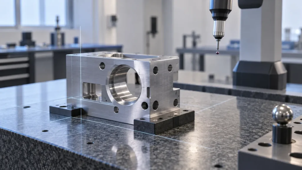
Ein Bezug muss an mehr als einer Stelle stabil sein
A datum may be theoretically correct but difficult to reproduce if it is too small, flexible, interrupted, or inaccessible. Ask whether the surface can be supported during machining, located during a secondary setup, and established during final inspection. If those three conditions use unrelated references, the drawing may create avoidable variation between operations.
Separate design intent from setup convenience
The easiest surface to clamp is not automatically the correct primary datum. A supplier can often design workholding around a functional datum, but only if the drawing makes that datum clear. When a manufacturing datum is needed in addition to a functional reference, document the relationship rather than silently substituting one for the other.
- Identify the assembly interface or load-bearing reference.
- Check whether the datum has enough area and rigidity for support.
- Confirm that the datum sequence constrains the intended degrees of freedom.
- Use the same logic in the inspection plan or explain any justified difference.
Ordnen Sie jede Kontrolle einem Fehlermodus zu
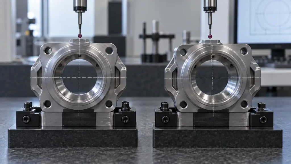
| Functional concern | Drawing information to review | Question for manufacturing and inspection |
|---|---|---|
| Fastener or dowel alignment | Hole size, position, datum order, depth, and MMC/RFS intent where applicable | Can the hole pattern be located and measured from the assembly reference? |
| Bearing or shaft rotation | Diameter limits, axis relationship, runout, shoulder, and surface requirement | Does the inspection method reproduce the rotating interface? |
| Sealing or seating | Flatness, profile, roughness, edge condition, and coating state | Will the reported result predict actual contact or leakage risk? |
| Moving clearance | Size limits, fit intent, temperature, lubrication, and surface condition | Are the two mating features specified and inspected as a pair? |
Avoid using a very tight general tolerance as a substitute for a missing functional callout. A broad drawing note can make a quote appear simple while leaving the supplier to guess which characteristics deserve additional setups or measurement.
Übersetzen Sie Beschriftungen in Prozessentscheidungen
GD&T affects more than inspection. Datums influence workholding; feature relationships influence setup sequence; tight profile or orientation controls may change tool access and finishing strategy. The drawing review should therefore happen before the route is treated as fixed.
Look for setup-sensitive relationships
Features cut in separate setups carry the risk of datum transfer. If a hole pattern on one face must relate closely to a bore created from another direction, the supplier should know that relationship early. The process may require probing, custom workholding, a combined mill-turn route, or a different order of roughing and finishing.
Review material and post-processing effects
Hardness, residual stress, thin walls, coatings, plating, anodizing, and polishing can change the final condition. A callout that is achievable before finishing may not remain correct afterward unless stock allowance, masking, or a post-process inspection stage is planned. State which dimensions apply to the machined condition and which apply after treatment.
For process selection and equipment context, the site’s CNC-Bearbeitungsmöglichkeiten page is a useful companion. It should complement the drawing review, not replace project-specific confirmation.
Definieren Sie, wie die Abnahme nachgewiesen wird

| Anforderungsart | Acceptance planning point | Record to clarify |
|---|---|---|
| Size and depth | Instrument access, resolution, temperature, and burr condition | Dimension report or gauge result |
| Position and orientation | Datum alignment, feature extraction, and material condition | GD&T result with the referenced datum frame |
| Surface or appearance | Measurement location, lighting, masking, and post-finish state | Surface or visual acceptance record |
Inspection planning should be proportional to risk. Not every ordinary dimension needs a full report, but critical characteristics should have an agreed method before production. The supplier’s quality and inspection information can help explain available verification routes; the drawing and purchase requirements still define the final acceptance scope.
Verwenden Sie eine Freigabe-Checkliste vor der Anfrage
Run this short review before sending a CNC machining drawing to a supplier:
- Revision control: confirm the drawing, model, notes, and file names refer to the same revision.
- Units and defaults: state units, decimal rules, general tolerances, and any governing drawing standard.
- Functional features: mark fits, seals, locating features, threads, rotating interfaces, and cosmetic zones.
- Datum logic: verify that primary, secondary, and tertiary datums represent assembly and inspection intent.
- Manufacturing feasibility: review access, wall thickness, deep features, workholding, material condition, and likely setup transfers.
- Post-processing: identify dimensions and surfaces that apply before or after heat treatment, coating, plating, or polishing.
- Acceptance: specify inspection records, sampling expectations, critical characteristics, and any functional test.
The strongest drawing does not contain the most callouts. It contains the fewest ambiguous decisions. When the functional intent, datum frame, material, finish, and inspection path agree, a CNC supplier can price the actual requirement instead of adding uncertainty to the estimate.
Häufig gestellte Fragen zu GD&T-Zeichnungsanforderungen
Is a 3D CAD model enough for a CNC quote?
Usually not when the part has controlled fits, GD&T, surface requirements, threads, special edge conditions, or inspection records. The model communicates nominal geometry, while the controlled drawing states tolerances, datums, finishes, revision information, and acceptance requirements.
Should every feature have a GD&T callout?
No. Use GD&T where form, orientation, location, or profile affects function. Ordinary dimensions and a suitable general tolerance can cover non-critical geometry. Adding tight controls everywhere may increase inspection and process cost without improving the part.
What makes a datum difficult for a CNC supplier?
A datum becomes difficult when it is flexible, too small, interrupted, inaccessible, or unrelated to the way the part is assembled. It should be possible to support or establish it consistently during machining and inspection, or the drawing should explain the intended reference method.
Do coatings change GD&T results?
They can change size, edge condition, surface friction, and the way a feature is measured. Identify whether a critical requirement applies before or after finishing, and review masking, allowance, and post-process inspection for mating or sealing features.
What should a buyer ask about a GD&T requirement?
Ask which datum reference frame will be used, which features are critical, how the control will be inspected, whether the process requires multiple setups, and whether material or finishing can change the result. These questions reveal risk before the drawing becomes a rejected batch.