
Exigences de dessin GD&T pour l'usinage CNC ne sont pas simplement une liste de symboles. Ils constituent le lien entre ce qu'une pièce doit faire, la façon dont elle sera positionnée pendant l'usinage et la façon dont le résultat fini sera vérifié. Un dessin peut indiquer chaque dimension nominale et laisser malgré tout un fournisseur incertain quant aux références, aux caractéristiques critiques, à la méthode d'inspection ou à l'état après finition. Un dessin prêt pour le devis rend ces décisions visibles sans prescrire un procédé inutilement coûteux.
Commencer par l'intention fonctionnelle de la pièce
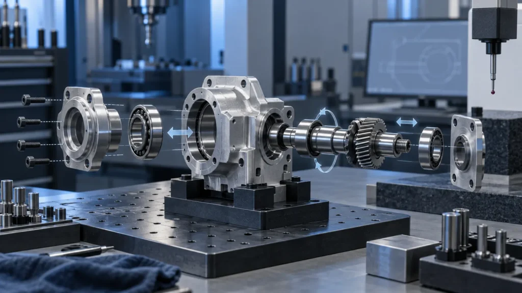
Avant d'ajouter un cadre de contrôle de caractéristique, identifiez la conséquence de la variation. Un motif de trous peut nécessiter un contrôle positionnel parce qu'une goupille doit entrer dans chaque trou. Une face peut nécessiter une perpendicularité parce qu'elle supporte un roulement. Un profil peut avoir de l'importance parce qu'un joint suit une surface profilée. Si le dessin ne révèle pas le mode de défaillance, un fournisseur peut consacrer des efforts à contrôler la mauvaise caractéristique.
Principe clé : Une spécification GD&T est utile lorsqu'elle décrit comment la caractéristique doit fonctionner dans l'assemblage et comment cette exigence peut être reproduite lors du contrôle.
- Caractéristiques de localisation : donnez la priorité aux relations de position et de référentiel.
- Interfaces en rotation : examinez ensemble la taille, l'orientation, le faux rond et l'état de surface.
- Surfaces d'étanchéité : tenez compte de la planéité, de la texture, des bavures et de l'état final du revêtement.
- Faces porteuses : vérifiez la forme et l'orientation par rapport au chemin de charge réel.
Pour la relation plus large entre les limites fonctionnelles, la stabilité du procédé et le contrôle, consultez le guide des tolérances d'usinage CNC. Cet article limite la discussion aux informations dont un fournisseur a besoin à partir d'un dessin contrôlé.
Constituer un dossier de dessin complet

| Élément du package | Ce qu'il doit clarifier | Conséquence courante en cas d'absence |
|---|---|---|
| Dessin contrôlé | Unités, tolérances par défaut, références, GD&T, filetages, arêtes et révision | Interprétations différentes du même modèle |
| Modèle CAO 3D | Géométrie nominale, profondeur de caractéristique, congés et forme usinable | Programmation FAO basée sur un fichier obsolète ou incomplet |
| Matériau et état | Nuance, revenu, dureté, traitement thermique ou autre état requis | Comportement de coupe inattendu, déformation ou performance |
| Notes de finition et d'acceptation | Traitement de surface, masquage, enregistrements d'inspection et limites d'emballage | Les dimensions ou l'aspect après traitement restent ambigus |
The package does not need to dictate every cutter or machining parameter. It does need to define the result, the reference system, and the conditions under which the result is accepted. That distinction gives the manufacturer room to select a stable route while protecting the engineering intent.
Rendre le cadre de référence de données utilisable
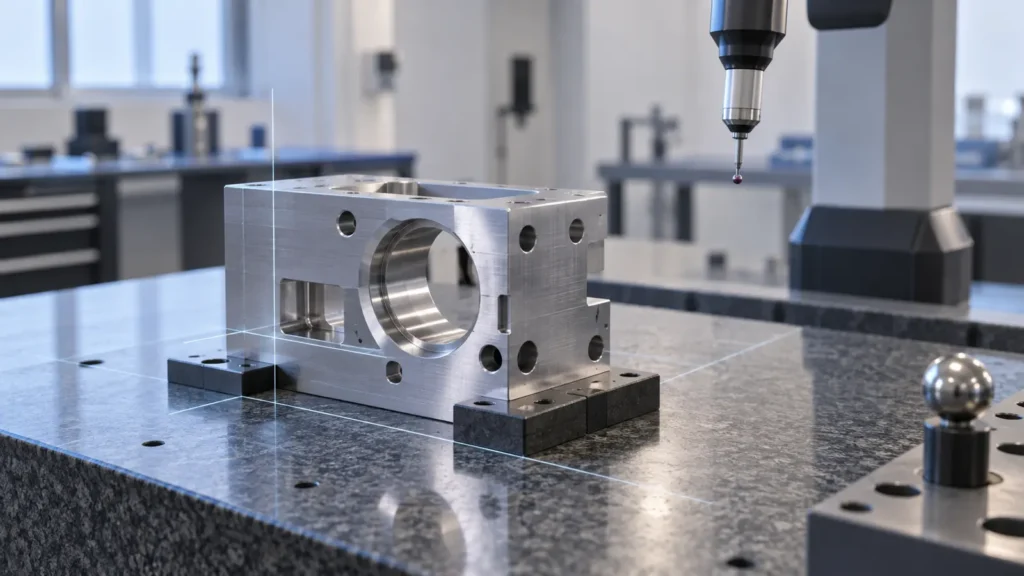
A datum must be stable in more than one place
A datum may be theoretically correct but difficult to reproduce if it is too small, flexible, interrupted, or inaccessible. Ask whether the surface can be supported during machining, located during a secondary setup, and established during final inspection. If those three conditions use unrelated references, the drawing may create avoidable variation between operations.
Separate design intent from setup convenience
The easiest surface to clamp is not automatically the correct primary datum. A supplier can often design workholding around a functional datum, but only if the drawing makes that datum clear. When a manufacturing datum is needed in addition to a functional reference, document the relationship rather than silently substituting one for the other.
- Identify the assembly interface or load-bearing reference.
- Check whether the datum has enough area and rigidity for support.
- Confirm that the datum sequence constrains the intended degrees of freedom.
- Use the same logic in the inspection plan or explain any justified difference.
Associer chaque contrôle à un mode de défaillance
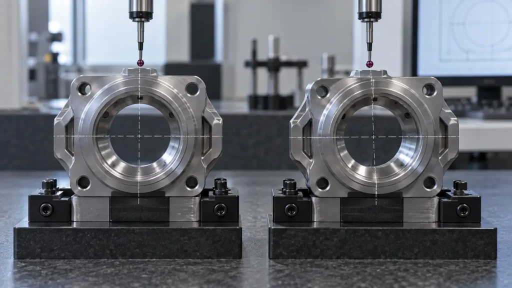
| Functional concern | Drawing information to review | Question for manufacturing and inspection |
|---|---|---|
| Fastener or dowel alignment | Hole size, position, datum order, depth, and MMC/RFS intent where applicable | Can the hole pattern be located and measured from the assembly reference? |
| Bearing or shaft rotation | Diameter limits, axis relationship, runout, shoulder, and surface requirement | Does the inspection method reproduce the rotating interface? |
| Sealing or seating | Flatness, profile, roughness, edge condition, and coating state | Will the reported result predict actual contact or leakage risk? |
| Moving clearance | Size limits, fit intent, temperature, lubrication, and surface condition | Are the two mating features specified and inspected as a pair? |
Avoid using a very tight general tolerance as a substitute for a missing functional callout. A broad drawing note can make a quote appear simple while leaving the supplier to guess which characteristics deserve additional setups or measurement.
Traduire les annotations en décisions de procédé
GD&T affects more than inspection. Datums influence workholding; feature relationships influence setup sequence; tight profile or orientation controls may change tool access and finishing strategy. The drawing review should therefore happen before the route is treated as fixed.
Look for setup-sensitive relationships
Features cut in separate setups carry the risk of datum transfer. If a hole pattern on one face must relate closely to a bore created from another direction, the supplier should know that relationship early. The process may require probing, custom workholding, a combined mill-turn route, or a different order of roughing and finishing.
Review material and post-processing effects
Hardness, residual stress, thin walls, coatings, plating, anodizing, and polishing can change the final condition. A callout that is achievable before finishing may not remain correct afterward unless stock allowance, masking, or a post-process inspection stage is planned. State which dimensions apply to the machined condition and which apply after treatment.
For process selection and equipment context, the site’s capacités d'usinage CNC page is a useful companion. It should complement the drawing review, not replace project-specific confirmation.
Définir comment l'acceptation sera prouvée

| Requirement type | Acceptance planning point | Record to clarify |
|---|---|---|
| Size and depth | Instrument access, resolution, temperature, and burr condition | Dimension report or gauge result |
| Position and orientation | Datum alignment, feature extraction, and material condition | GD&T result with the referenced datum frame |
| Surface or appearance | Measurement location, lighting, masking, and post-finish state | Surface or visual acceptance record |
Inspection planning should be proportional to risk. Not every ordinary dimension needs a full report, but critical characteristics should have an agreed method before production. The supplier’s quality and inspection information can help explain available verification routes; the drawing and purchase requirements still define the final acceptance scope.
Utiliser une liste de contrôle de diffusion avant l'appel d'offres
Run this short review before sending a CNC machining drawing to a supplier:
- Revision control: confirm the drawing, model, notes, and file names refer to the same revision.
- Units and defaults: state units, decimal rules, general tolerances, and any governing drawing standard.
- Functional features: mark fits, seals, locating features, threads, rotating interfaces, and cosmetic zones.
- Datum logic: verify that primary, secondary, and tertiary datums represent assembly and inspection intent.
- Manufacturing feasibility: review access, wall thickness, deep features, workholding, material condition, and likely setup transfers.
- Post-processing: identify dimensions and surfaces that apply before or after heat treatment, coating, plating, or polishing.
- Acceptance: specify inspection records, sampling expectations, critical characteristics, and any functional test.
The strongest drawing does not contain the most callouts. It contains the fewest ambiguous decisions. When the functional intent, datum frame, material, finish, and inspection path agree, a CNC supplier can price the actual requirement instead of adding uncertainty to the estimate.
FAQ sur les exigences de dessin GD&T
Is a 3D CAD model enough for a CNC quote?
Usually not when the part has controlled fits, GD&T, surface requirements, threads, special edge conditions, or inspection records. The model communicates nominal geometry, while the controlled drawing states tolerances, datums, finishes, revision information, and acceptance requirements.
Should every feature have a GD&T callout?
No. Use GD&T where form, orientation, location, or profile affects function. Ordinary dimensions and a suitable general tolerance can cover non-critical geometry. Adding tight controls everywhere may increase inspection and process cost without improving the part.
What makes a datum difficult for a CNC supplier?
A datum becomes difficult when it is flexible, too small, interrupted, inaccessible, or unrelated to the way the part is assembled. It should be possible to support or establish it consistently during machining and inspection, or the drawing should explain the intended reference method.
Do coatings change GD&T results?
They can change size, edge condition, surface friction, and the way a feature is measured. Identify whether a critical requirement applies before or after finishing, and review masking, allowance, and post-process inspection for mating or sealing features.
What should a buyer ask about a GD&T requirement?
Ask which datum reference frame will be used, which features are critical, how the control will be inspected, whether the process requires multiple setups, and whether material or finishing can change the result. These questions reveal risk before the drawing becomes a rejected batch.