
Requisitos de planos de GD&T para el mecanizado CNC no son solo una lista de símbolos. Son el vínculo entre lo que debe hacer una pieza, cómo se ubicará durante el mecanizado y cómo se verificará el resultado final. Un plano puede mostrar cada dimensión nominal y aun así dejar a un proveedor con dudas sobre los datums, las características críticas, el método de inspección o la condición después del acabado. Un plano listo para cotizar hace visibles esas decisiones sin prescribir un proceso innecesariamente costoso.
Comience con la intención funcional de la pieza
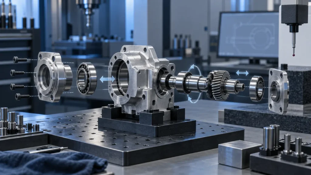
Antes de agregar un marco de control de característica, identifique la consecuencia de la variación. Un patrón de agujeros puede necesitar control de posición porque una espiga debe entrar en cada agujero. Una cara puede necesitar perpendicularidad porque soporta un rodamiento. Un perfil puede importar porque un sello sigue una superficie contorneada. Si el plano no revela el modo de falla, un proveedor puede gastar esfuerzo controlando la característica equivocada.
Principio clave: Una llamada de GD&T es útil cuando describe cómo debe funcionar la característica en el ensamblaje y cómo ese requisito puede reproducirse en la inspección.
- Características de localización: priorizar la posición y las relaciones de datum.
- Interfaces giratorias: revisar el tamaño, la orientación, el descentramiento y la condición superficial en conjunto.
- Superficies de sellado: considerar la planitud, la textura, las rebabas y la condición final del recubrimiento.
- Caras de carga: verificar la forma y la orientación en relación con la trayectoria real de carga.
Para la relación más amplia entre los límites funcionales, la estabilidad del proceso y la inspección, consulte el guía de tolerancias de mecanizado CNC. Este artículo limita la discusión a la información que un proveedor necesita de un plano controlado.
Elabore un paquete de planos completo

| Elemento del paquete | Qué debe aclarar | Consecuencia común cuando falta |
|---|---|---|
| Plano controlado | Unidades, tolerancias predeterminadas, datums, GD&T, roscas, bordes y revisión | Diferentes interpretaciones del mismo modelo |
| Modelo CAD 3D | Geometría nominal, profundidad de características, empalmes y forma mecanizable | Programación CAM basada en un archivo desactualizado o incompleto |
| Material y condición | Grado, temple, dureza, tratamiento térmico u otra condición requerida | Comportamiento de corte inesperado, distorsión o rendimiento |
| Notas de acabado y aceptación | Tratamiento superficial, enmascarado, registros de inspección y límites de embalaje | Las dimensiones o la apariencia posteriores al proceso siguen siendo ambiguas |
El paquete no necesita dictar cada cortador o parámetro de mecanizado. Sí necesita definir el resultado, el sistema de referencia y las condiciones bajo las cuales se acepta el resultado. Esa distinción le da al fabricante margen para seleccionar una ruta estable mientras protege la intención de ingeniería.
Haga utilizable el marco de referencia de datums
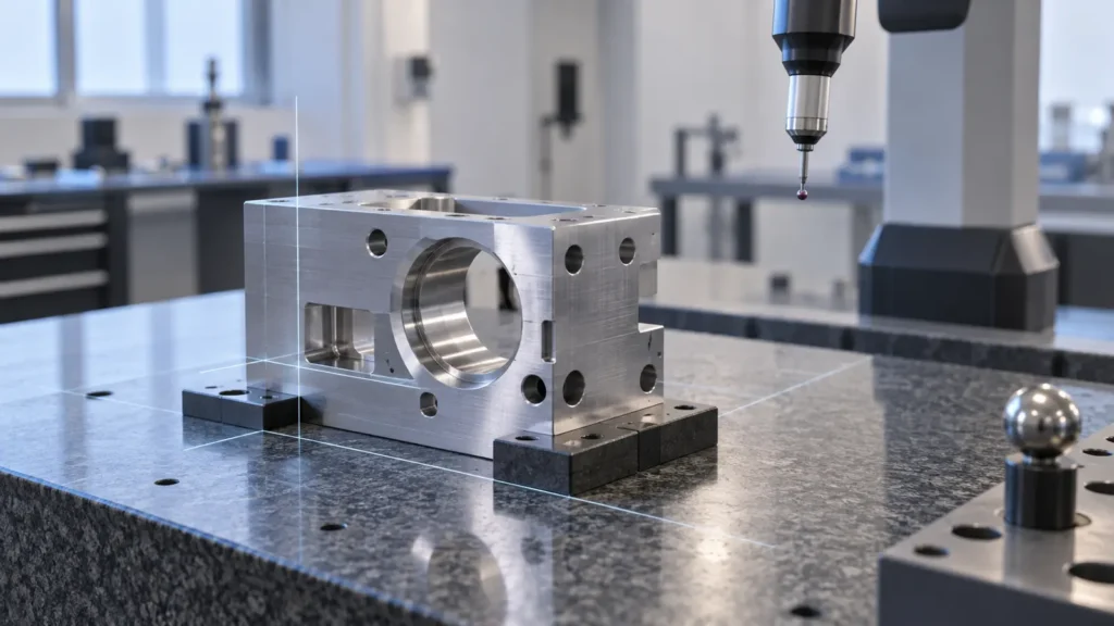
Un datum debe ser estable en más de un lugar
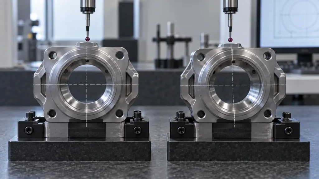
Un dato puede ser teóricamente correcto pero difícil de reproducir si es demasiado pequeño, flexible, interrumpido o inaccesible. Pregunte si la superficie puede ser soportada durante el mecanizado, localizada durante una configuración secundaria y establecida durante la inspección final. Si esas tres condiciones utilizan referencias no relacionadas, el plano puede crear una variación evitable entre operaciones.
Separar la intención de diseño de la conveniencia de configuración
La superficie más fácil de sujetar no es automáticamente el dato primario correcto. Un proveedor a menudo puede diseñar el sistema de sujeción en torno a un dato funcional, pero solo si el plano deja claro ese dato. Cuando se necesita un dato de fabricación además de una referencia funcional, documente la relación en lugar de sustituir silenciosamente uno por el otro.
- Identificar la interfaz de ensamblaje o la referencia de carga.
- Verificar si el dato tiene suficiente área y rigidez para el soporte.
- Confirmar que la secuencia de datos restringe los grados de libertad previstos.
- Utilizar la misma lógica en el plan de inspección o explicar cualquier diferencia justificada.
Relacione cada control con un modo de falla
| Preocupación funcional | Información del plano a revisar | Pregunta para fabricación e inspección |
|---|---|---|
| Alineación de sujetadores o pasadores | Tamaño del agujero, posición, orden de datos, profundidad e intención MMC/RFS donde corresponda | ¿Se puede localizar y medir el patrón de agujeros desde la referencia de ensamblaje? |
| Rotación de rodamiento o eje | Diameter limits, axis relationship, runout, shoulder, and surface requirement | Does the inspection method reproduce the rotating interface? |
| Sealing or seating | Flatness, profile, roughness, edge condition, and coating state | Will the reported result predict actual contact or leakage risk? |
| Moving clearance | Size limits, fit intent, temperature, lubrication, and surface condition | Are the two mating features specified and inspected as a pair? |
Avoid using a very tight general tolerance as a substitute for a missing functional callout. A broad drawing note can make a quote appear simple while leaving the supplier to guess which characteristics deserve additional setups or measurement.
Traduzca las anotaciones en decisiones de proceso
GD&T affects more than inspection. Datums influence workholding; feature relationships influence setup sequence; tight profile or orientation controls may change tool access and finishing strategy. The drawing review should therefore happen before the route is treated as fixed.
Look for setup-sensitive relationships
Features cut in separate setups carry the risk of datum transfer. If a hole pattern on one face must relate closely to a bore created from another direction, the supplier should know that relationship early. The process may require probing, custom workholding, a combined mill-turn route, or a different order of roughing and finishing.
Review material and post-processing effects
Hardness, residual stress, thin walls, coatings, plating, anodizing, and polishing can change the final condition. A callout that is achievable before finishing may not remain correct afterward unless stock allowance, masking, or a post-process inspection stage is planned. State which dimensions apply to the machined condition and which apply after treatment.
For process selection and equipment context, the site’s capacidades de mecanizado CNC page is a useful companion. It should complement the drawing review, not replace project-specific confirmation.
Defina cómo se demostrará la aceptación

| Tipo de requisito | Acceptance planning point | Record to clarify |
|---|---|---|
| Size and depth | Instrument access, resolution, temperature, and burr condition | Dimension report or gauge result |
| Position and orientation | Datum alignment, feature extraction, and material condition | GD&T result with the referenced datum frame |
| Surface or appearance | Measurement location, lighting, masking, and post-finish state | Surface or visual acceptance record |
Inspection planning should be proportional to risk. Not every ordinary dimension needs a full report, but critical characteristics should have an agreed method before production. The supplier’s quality and inspection information can help explain available verification routes; the drawing and purchase requirements still define the final acceptance scope.
Use una lista de verificación de liberación antes de la RFQ
Run this short review before sending a CNC machining drawing to a supplier:
- Revision control: confirm the drawing, model, notes, and file names refer to the same revision.
- Units and defaults: state units, decimal rules, general tolerances, and any governing drawing standard.
- Functional features: mark fits, seals, locating features, threads, rotating interfaces, and cosmetic zones.
- Datum logic: verify that primary, secondary, and tertiary datums represent assembly and inspection intent.
- Manufacturing feasibility: review access, wall thickness, deep features, workholding, material condition, and likely setup transfers.
- Post-processing: identify dimensions and surfaces that apply before or after heat treatment, coating, plating, or polishing.
- Acceptance: specify inspection records, sampling expectations, critical characteristics, and any functional test.
The strongest drawing does not contain the most callouts. It contains the fewest ambiguous decisions. When the functional intent, datum frame, material, finish, and inspection path agree, a CNC supplier can price the actual requirement instead of adding uncertainty to the estimate.
Preguntas frecuentes sobre requisitos de planos de GD&T
Is a 3D CAD model enough for a CNC quote?
Usually not when the part has controlled fits, GD&T, surface requirements, threads, special edge conditions, or inspection records. The model communicates nominal geometry, while the controlled drawing states tolerances, datums, finishes, revision information, and acceptance requirements.
Should every feature have a GD&T callout?
No. Use GD&T where form, orientation, location, or profile affects function. Ordinary dimensions and a suitable general tolerance can cover non-critical geometry. Adding tight controls everywhere may increase inspection and process cost without improving the part.
What makes a datum difficult for a CNC supplier?
A datum becomes difficult when it is flexible, too small, interrupted, inaccessible, or unrelated to the way the part is assembled. It should be possible to support or establish it consistently during machining and inspection, or the drawing should explain the intended reference method.
Do coatings change GD&T results?
They can change size, edge condition, surface friction, and the way a feature is measured. Identify whether a critical requirement applies before or after finishing, and review masking, allowance, and post-process inspection for mating or sealing features.
What should a buyer ask about a GD&T requirement?
Ask which datum reference frame will be used, which features are critical, how the control will be inspected, whether the process requires multiple setups, and whether material or finishing can change the result. These questions reveal risk before the drawing becomes a rejected batch.