
CNC-Bearbeitungstoleranzen sind die kontrollierten Grenzen um die Nennmaße einer Zeichnung. Sie bestimmen, ob eine Welle in eine Bohrung passt, ob ein Gehäuse dicht ist, ob eine Baugruppe ausgerichtet ist und wie viel Prozess- und Prüfdisziplin ein Teil erfordert. Die richtige Toleranz ist nicht der engste Wert, den eine Maschine erreichen könnte. Sie ist die lockerste Grenze, die die Funktion schützt, gestützt auf einen stabilen Aufbau, eine geeignete Materialstrategie und eine definierte Messmethode.
Toleranz beginnt mit der Funktion
Fragen Sie, was das Merkmal tun muss
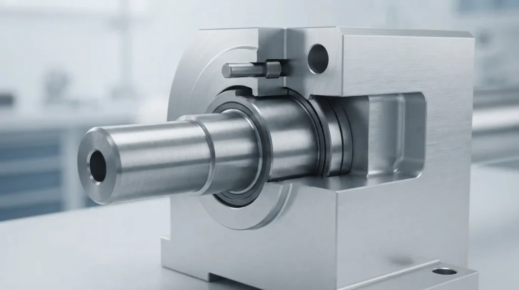
Bevor Sie eine numerische Toleranz festlegen, beschreiben Sie die Funktion des Merkmals. Positioniert es ein anderes Teil, trägt es eine Last, kontrolliert es einen Spalt, erzeugt es eine Dichtung, führt es eine Bewegung, überträgt es Wärme oder definiert es eine Erscheinungsgrenze? Die Antwort bestimmt, ob die Priorität auf Größe, Position, Orientierung, Form, Oberflächenbeschaffenheit oder einer Kombination von Kontrollen liegt.
- Lage: Bohrungen und Bezüge können eine kontrollierte Position erfordern, damit Verbindungselemente, Stifte oder Schnittstellen ausgerichtet sind.
- Größe: Wellen, Bohrungen, Nuten und Taschen können Grenzwerte erfordern, die eine Spiel-, Übergangs- oder Presspassung unterstützen.
- Form: Ebenheit, Rundheit, Geradheit oder Zylindrizität können von Bedeutung sein, selbst wenn die Gesamtgröße akzeptabel ist.
- Orientierung: Parallelität, Rechtwinkligkeit und Winkelkontrolle können bestimmen, ob eine Baugruppe korrekt sitzt.
- Oberfläche: Rauheit, Gratzustand, Beschichtungsdicke und kosmetische Abweichungen können Dichtheit, Verschleiß oder Aussehen beeinflussen.
Für einen umfassenderen Überblick darüber, wie Zeichnungsanforderungen zu einem fertigen Teil werden, beginnen Sie mit der Überblick über die CNC-Bearbeitung. Die Toleranzplanung sollte Teil des Fertigungsgesprächs sein, bevor ein Angebot herausgegeben wird.
Eine praktische Toleranzhierarchie
| Zeichnungspriorität | Typischer Zweck | Was der Lieferant wissen muss |
|---|---|---|
| Allgemeine Merkmale | Gesamtform, unkritische Bohrungen, Freigangsmerkmale und Stützgeometrie | Der zutreffende allgemeine Toleranzhinweis und die Einheiten |
| Gesteuerte Merkmale | Schnittstellen, Positioniermerkmale, Gewindeelemente und funktionale Spalte | Das individuelle Grenzmaß, die Passungsabsicht, die Bezugsangabe und der Oberflächenzustand |
| Kritische Merkmale | Merkmale, die Sicherheit, Dichtheit, Bewegung, Druck oder regulatorische Leistung beeinflussen | Die Abnahmemethode, die Erwartung an den Prüfbericht und die Anforderung an die Änderungskontrolle |
Warum eine einzelne pauschale Toleranz Verwirrung stiften kann
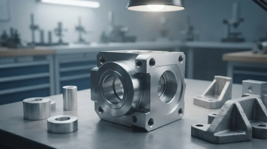
Ein pauschaler Hinweis kann für viele unkritische Maße angemessen sein, aber er kann nicht die Passung jeder Bohrung, die Position jedes Lochbildes oder die Ebenheit jeder Dichtfläche erklären. Wenn ein Merkmal wichtig genug ist, um die Montage zu beeinflussen, benennen Sie es direkt. Dies verringert Auslegungsunterschiede zwischen Konstruktion, Fertigung und Prüfung.
Wann allgemeine Toleranzen ausreichen
Allgemeintoleranzen funktionieren gut, wenn ein Maß genügend funktionale Reserve hat und nicht mit einer Präzisionsschnittstelle zusammenwirkt. Sie können Zeichnungen vereinfachen, unnötige Prüfungen reduzieren und einem Lieferanten helfen, das Teil konsistent anzubieten. Die Zeichnung muss dennoch angeben, welche allgemeine Norm oder Unternehmensregel gilt; “auf Standard bearbeiten” ist keine vollständige Anforderung.
- Verwenden Sie den allgemeinen Hinweis für Maße, die nicht Passung, Dichtheit, Ausrichtung oder gesteuerte Bewegung bestimmen.
- Use individual callouts for bearing seats, mating diameters, locating pins, sealing faces, and critical hole patterns.
- Keep units and decimal conventions consistent across the drawing and model.
- Do not use a tight general tolerance to compensate for an unclear functional requirement.
The goal is not to make every dimension “precision.” The goal is to make the critical dimensions visible and leave the remaining geometry manufacturable. This distinction is especially important when a project moves from a prototype to a repeat production run.
Toleranzen auf Merkmalsebene, die Aufmerksamkeit verdienen

Holes, bores, and threads
For a hole, size is only one part of the requirement. Position, perpendicularity, depth, entry condition, burr control, and the fit of the mating component may matter just as much. A thread callout should identify the thread form and size, depth or through condition, and any requirement for a controlled fit or inspection gauge.
Mating diameters and fits
Shaft-and-bore relationships should be specified as a fit system or as coordinated limits, not as two unrelated dimensions. Consider temperature, coating or plating thickness, lubrication, assembly method, and whether the joint must be removable. A fit that works at room temperature may behave differently in service.
Thin walls, deep pockets, and large flat surfaces
Thin sections can deflect during cutting or inspection. Deep pockets can magnify tool deflection and corner-radius limitations. Large flat surfaces can respond to residual stress, heat, or the order in which material is removed. These features need a tolerance strategy that considers geometry and process sequence, not just the nominal size.
GD&T, Passungen und Bezugsstrategie
Build the datum structure around assembly
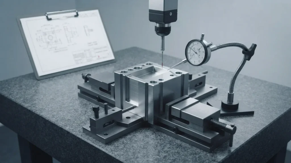
The primary datum should represent how the part is located in the assembly or inspection setup. Secondary and tertiary datums should constrain the remaining degrees of freedom in a way that reflects the real interface. If the drawing datum scheme does not resemble the way the part is assembled, a feature may pass one measurement method and still fail at assembly.
Do not stack controls without a reason
Size, position, profile, flatness, and perpendicularity can interact. Applying all of them tightly may over-constrain the part or create inspection disputes. Select the control that best describes the failure mode, then define the acceptance condition clearly. If the functional requirement is unclear, a design-for-manufacturing review can often simplify the callout.
For tolerance-critical work, link the drawing requirement to a defined quality and inspection approach. The measurement method should be decided before production, not after a dimension is found outside the limit.
Was bringt eine Toleranz außer Kontrolle?
A programmed coordinate is not the same as a stable finished dimension. The result is influenced by the complete process chain, including:
- Machine condition and thermal state: temperature changes can shift the relationship between the tool, workpiece, and probing or measurement reference.
- Tool wear and deflection: cutting force, tool length, reach, and wear can affect size and form, especially on hard materials or deep features.
- Workholding: clamping can distort flexible parts, while poor location or insufficient support can allow movement during cutting.
- Material behavior: residual stress, hardness variation, moisture, and thermal expansion can change the part during or after machining.
- Process sequence: roughing, stress relief, finishing, deburring, heat treatment, and coating can all alter the final condition.
- Inspection method: instrument resolution, calibration, temperature, fixturing, datum alignment, and operator method affect the reported result.
This is why a supplier should review the full drawing package instead of quoting a tolerance number in isolation. The site’s CNC capabilities overview can provide process context, but the drawing, material, quantity, and inspection requirement determine what should be planned for a specific part.
Auswirkungen von Material, Oberfläche und Prüfung
| Condition | Potential effect | Planning response |
|---|---|---|
| Hard or difficult-to-machine material | Higher cutting force, tool wear, heat, and longer finishing cycles | Review tool access, workholding, sequencing, and verification before promising a limit |
| Plastic or flexible material | Deflection, moisture response, creep, or size change after unclamping | Define support, conditioning, measurement timing, and functional allowance |
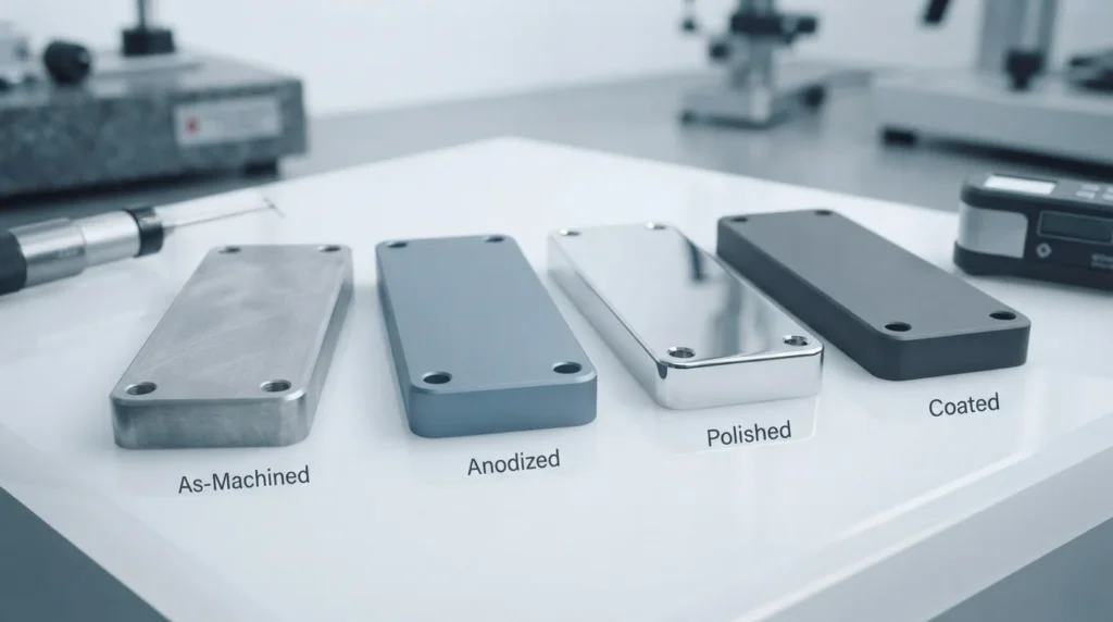
| Anodizing, plating, coating, or passivation | Added thickness, edge build-up, masking variation, or altered surface friction | Identify post-finish critical dimensions and whether they are measured before or after finishing |
| Tight inspection requirement | More measurement time and greater sensitivity to datum, temperature, and method | Define the report, sampling plan, equipment, and acceptance reference in advance |
A tolerance is only meaningful when the inspection method can resolve it and the measurement setup represents the part’s function. If the part is temperature-sensitive, flexible, or coated, include those conditions in the quality plan rather than treating them as informal shop details.
Ein Arbeitsablauf zur Zeichnungsprüfung
Use this sequence before requesting a quote or releasing a revision:
- Mark functional interfaces: identify fits, seals, locating features, load paths, and cosmetic surfaces.
- Separate general and critical dimensions: apply a suitable general note, then call out the features that truly need individual control.
- Check datum logic: make sure the drawing reference frame represents assembly and inspection conditions.
- Review process risk: consider material, wall thickness, depth, tool reach, workholding, finishing, and expected quantity.
- Define verification: state whether the requirement is checked with gauges, hand instruments, optical measurement, CMM, functional assembly, or another method.
- Confirm post-processing condition: distinguish dimensions measured before and after heat treatment, coating, plating, or other finishing.
- Ask for manufacturability feedback: let the supplier identify a callout that is tighter than the function requires or a requirement that lacks a clear acceptance method.
When the drawing, model, material, quantity, and inspection requirements are ready, send them through the CNC machining quote workflow. A clear package gives the supplier a chance to price the required precision instead of adding a risk buffer for unknowns.
Häufig gestellte Fragen zu CNC-Bearbeitungstoleranzen
What is a typical CNC machining tolerance?
There is no single tolerance that applies to every CNC part. The practical limit depends on the process, material, feature geometry, workholding, thermal condition, quantity, finish, and inspection method. Use the drawing’s general tolerance for non-critical features and define tighter limits only where the function requires them.
Is a tighter tolerance always better?
No. A tighter limit can add machining time, finishing effort, inspection time, and scrap risk without improving performance. The better specification is the loosest tolerance that reliably protects fit, function, sealing, motion, strength, or appearance.
Should I use plus-or-minus dimensions or GD&T?
Use the notation that communicates the failure mode most clearly. Plus-or-minus limits are useful for size; GD&T is often clearer for position, orientation, form, and profile. A mixed drawing is acceptable when each control has a defined purpose and the datum scheme is consistent.
Do surface finishes affect CNC tolerances?
They can. Coatings may add thickness, polishing removes material, and roughness can affect how a gauge, seal, or mating surface behaves. State whether a critical dimension applies before or after finishing and identify any masking or coating-thickness requirement.
What should I send a CNC supplier to review tolerance requirements?
Provide the current CAD model, controlled drawing, material and condition, quantity, revision, critical dimensions, GD&T, surface finish, post-processing, inspection report expectations, and the part’s functional context. That information supports a more realistic process and quote review.