
Tantalum machining should be planned from the exact grade and supplied condition, not from a generic refractory-metal recipe. The metal’s ductile, adhesive cutting behavior can produce high forces, thick flowing chips, and a torn surface when the tool-work interface is unstable; published research describes severe chip-flow and surface-quality challenges. That makes a sharp edge, secure workholding, controlled coolant practice, and a realistic inspection plan central to the process. A parameter table from another grade, product form, or machine is not a release specification.
Before committing an expensive blank, align the drawing, material certificate, and manufacturing route. The key decision is whether the finished geometry and surface can be produced and verified from the specific stock condition supplied for the job.
Specify the material before choosing the cut
Confirm whether the order calls for commercially pure tantalum or a named alloy, and identify the applicable material specification, product form, size, and condition. A plate and a bar can carry different working histories and create different machining support problems. If the drawing depends on chemistry, mechanical properties, purity, or traceability, state the required certificate and link it to the delivered heat or lot.
Also define the part’s service environment and any cleanliness or contamination controls. Tantalum is selected for demanding corrosion and temperature applications, but the suitability of a particular grade depends on the actual medium, temperature, and design. The site’s high-temperature materials overview and corrosion-resistant materials page provide broad selection context, not a chemical compatibility approval.
Why tantalum can smear, tear, or load the tool
Research on cutting tantalum reports thick chips, large cutting forces, and poor surface quality associated with complex plastic flow. In practice, a tool that rubs or loses its edge can worsen heat and material adhesion at the interface. A surface tear is therefore a process signal, not merely a cosmetic defect. Distinguish a built-up deposit on the tool from damage transferred to the component, and inspect whether defects repeat at a specific feed direction, corner, or interrupted feature.
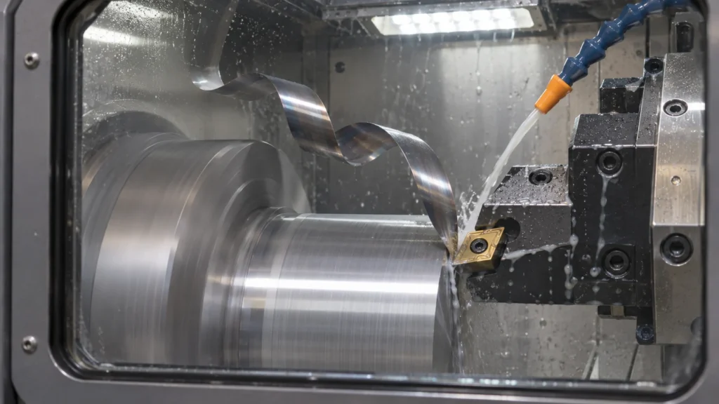
Supplier fabrication notes often recommend lubrication and attention to tool condition, but recommendations vary with grade and operation. Confirm coolant compatibility, filtration, cleanliness, and disposal requirements with the material and fluid suppliers. Do not copy a legacy cutting-speed chart without matching its tool geometry, stock condition, and test setup.
| Process observation | Possible cause to investigate | Control or evidence |
|---|---|---|
| Dragged or torn finish | Rubbing, adhesion, or a worn edge | Inspect tool edge; review engagement and coolant delivery |
| High or unstable load | Thick chip flow, interrupted cut, or weak support | Check setup stiffness, stock allowance, and feature sequence |
| Localized scratches | Chip recutting, handling, or debris trapped at the interface | Review chip path, cleaning, and part handling |
| Variation after unclamping | Constraint or stress release | Compare clamped and free-state measurements during first-off |
Build the route around support and access
Start by mapping the datum surfaces, thin walls, deep features, and any surface that cannot be marked. Choose a sequence that supports the part near the active cut and avoids leaving a fragile edge unsupported too early. On a plate, alternate removal or preserve a temporary web where the geometry allows; on a turned part, keep the overhang controlled as diameter and stiffness change. These are planning principles, not a substitute for a job-specific fixture and process trial.
Reserve stock for a continuous finishing pass and keep the finish tool’s path away from burr-prone exits when possible. Where tool access forces an interrupted cut, address that in the first-off review instead of applying a generic parameter reduction across the whole program. Document approved tool, coolant, and sequence changes so the accepted process can be repeated.
Protect surface integrity and cleanliness
For a critical sealing, corrosive-service, or fatigue-sensitive surface, the drawing should say what must be controlled and how it will be checked. “Smooth” is not a measurable acceptance criterion. Specify the relevant roughness parameter and measurement direction only when the design owner has chosen them; include geometry, cutoff or instrument method where needed to make results comparable. Add a visual or other approved inspection for tears, embedded debris, and edge damage if those can affect function.

Keep coolant residue and shop contamination from becoming a downstream problem. Define cleaning and packaging expectations when the part will enter a controlled assembly or chemical service. The CNC milling page describes the process category; confirm the actual tantalum grade, size, and inspection requirements during quotation rather than assuming a generic capability statement covers them.
Verify the part against a defined boundary
Measure critical features after the part is free from the fixture and in the agreed inspection condition. For thin or asymmetric parts, first-off measurements at intermediate steps can reveal movement before final stock is removed. Keep the datum scheme consistent with the drawing and identify whether a dimension is checked before or after any cleaning or finish operation.
Acceptance should tie together material identity, dimensions, functional surface condition, and required records. If a flaw appears, obtain engineering disposition rather than polishing or blending it away without authorization. That preserves evidence about the process and avoids changing the geometry that the drawing controls.
A practical tantalum RFQ checklist
- Exact grade/alloy, product form, condition, specification, and certificate scope.
- Part envelope, thin walls, deep features, datum scheme, and critical surfaces.
- Required surface-finish parameter, measurement direction, and defect acceptance method.
- Coolant, cleaning, contamination, and packaging restrictions, if any.
- First-article, traceability, and post-machining inspection deliverables.
This information lets the supplier identify process risk before stock is committed and keeps the accepted requirements tied to the delivered material and finished part.