
Choose MIC-6 when the plate’s main job is to stay flat through pocketing, fixture machining, or repeated hole patterns; choose 6061 plate when the part must carry structural load, hold demanding threaded features, or accept a specified wrought-alloy condition and finish. The comparison is between a cast tooling-plate product and a family of wrought 6061 products, so “6061” alone is not a complete counterpart.
For a fixture base, vacuum plate, inspection nest, or machine component, the important question is what must remain true after material is removed. Flatness and dimensional stability can be more valuable than strength for a lightly loaded tool plate. For a structural component, a flat starting surface cannot compensate for an alloy condition that does not meet the load, thread, or joining requirements.
These are different product forms
MIC-6 is a trade name used for cast aluminum tooling plate. It is supplied as plate intended for flat tooling, fixtures, bases, and similar applications. 6061 is a wrought alloy that may be supplied in different tempers and product forms, including plate. Those forms and conditions have their own mechanical and dimensional requirements. Comparing “MIC-6” to “6061” without stating temper, thickness, and plate specification leaves important assumptions unresolved.
A cast tooling plate may arrive with both faces prepared to a stated flatness and surface condition. A 6061 plate may offer a different balance of strength and fabrication options, but its actual flatness and stress condition depend on the specified product. Check the maker’s data sheet and the purchase order for the exact tolerance. Do not treat a seller’s typical property table as a guarantee for every thickness or supplier lot. The site’s MIC-6 material page and 6061-T6/T651 material page provide grade context.
When flatness drives the plate choice
MIC-6 is worth evaluating when the plate is a tooling element and the machined geometry removes a large amount of material from one side. Pockets, vacuum channels, mounting grids, and reference surfaces can unbalance the blank. A plate designed for low movement during machining may reduce the amount of corrective face machining needed, but the final result still depends on support, clamping, toolpath, stock size, and how much material is removed.
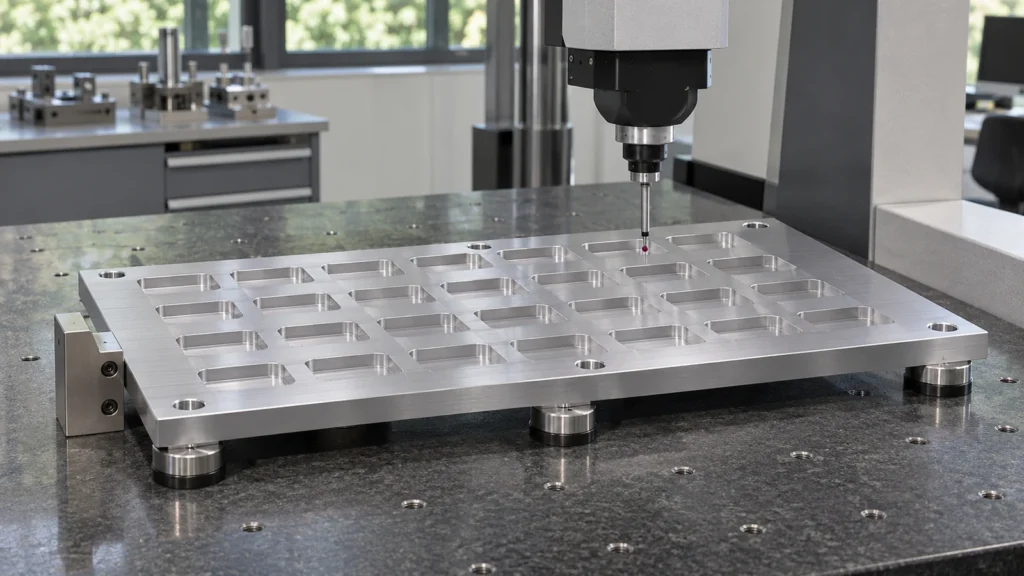
Think about the plate after it is released from the fixture. Flatness measured while clamped can disappear when the clamps are removed. If the part’s function depends on a flat mounting plane, define how it is supported and measured in the drawing. If only a small region matters, identify that region and its datum relationship rather than applying a blanket flatness requirement to every face.
6061-T651 plate may be a better starting point when a wrought alloy and stress-relieved condition are specified, but its suitability should be evaluated against the real plate thickness and material documentation. A “stress relieved” label does not eliminate the need to plan balanced roughing and finishing. For a high-removal plate, consider whether a roughing stage, unclamping, and datum recovery will protect the final flat surface.
When the plate must carry load or hold threads
Tooling plate is commonly selected for flatness and machinability, not because it is interchangeable with a structural alloy plate. If the component sees bending, impact, bolt preload, or repeated clamping, compare the required load and attachment details with the exact material condition. A plate can look dimensionally excellent and still be a poor choice if tapped holes strip, bearing surfaces deform, or the component yields under service loads.
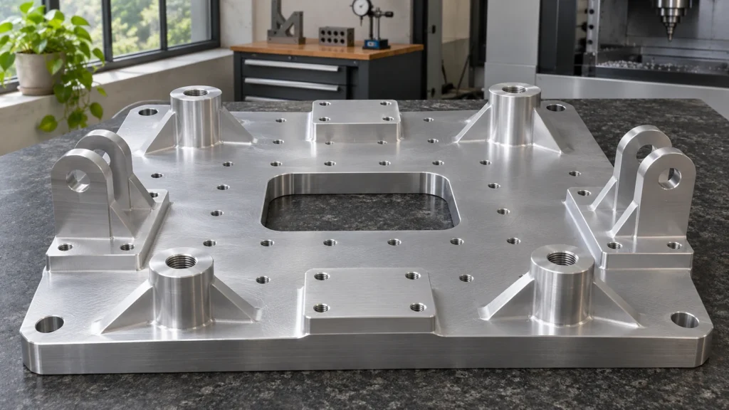
Threads deserve their own review. Engagement length, parent material strength, fastener grade, installation torque, and repeated assembly all affect thread performance. When the design demands high clamp force or frequent servicing, a stronger plate, steel insert, through-bolt, or replaceable threaded element may be more suitable. Select these options from the assembly load and service life, not from an assumed “standard” thread capacity.
Surface finish can also decide the comparison. If the part needs a cosmetic anodized appearance, confirm that the chosen plate product can deliver the specified color and uniformity. Cast structures can respond differently from wrought 6061. If appearance is not functional, a protective finish or an as-machined condition may be adequate, subject to the environment and drawing. Specify appearance acceptance using a representative sample or objective criteria where the project requires it.
Plan machining around stress and material removal
Use a machining plan that preserves a stable datum and avoids concentrating removal on one face too early. Rough both sides where geometry allows, leave a controlled finish allowance, and reassess the blank after roughing. The exact sequence depends on thickness, pocket layout, clamping, material condition, and the size of the finished plate. A rule of thumb cannot predict movement for every blank.
Also distinguish a plate that serves as a fixture from a plate that becomes a customer component. A fixture may prioritize flatness, hole-grid location, and serviceability. A finished component may prioritize strength, sealing faces, threads, corrosion protection, or appearance. A material change that works for a fixture can be unacceptable in a load-bearing assembly or a regulated product.
Write the purchase requirement around function
- Name the product: cast tooling plate or wrought 6061 plate, with the exact temper and governing specification where applicable.
- State thickness, size, flatness, parallelism, surface finish, and the inspection method or reference surfaces.
- Identify pockets, hole grids, tapped features, and faces that must remain stable after release from the fixture.
- Define load, fastener, and repeated-assembly requirements before selecting a low-strength tooling material.
- Specify whether anodizing is cosmetic or protective, and define acceptable variation if appearance matters.
- Require approval for a product-form or supplier substitution; do not accept “aluminum tooling plate” as a complete replacement description.
MIC-6 and 6061 can both be useful CNC plate materials, but they solve different problems. Select the plate around the part’s functional duty, the amount and symmetry of machining, and the evidence required at inspection. That keeps “flat enough” and “strong enough” tied to the same controlled design decision.