
Nitronic 60 is worth considering when two metal parts slide or rub under load and galling is a credible failure mode, but naming the alloy alone does not make a contact pair safe. The drawing and purchase specification should identify the mating material, motion, load, lubrication or dry-running condition, environment, surface finish, and the evidence used for acceptance. The alloy is a candidate, not a substitute for a contact-system review. Its performance depends on the opposing surface and operating conditions, while the delivered product form and condition still matter to machining and inspection.
For CNC parts, the useful question is therefore not simply “Can Nitronic 60 be machined?” It is whether the finished geometry, surface, and material records support the intended anti-galling function without creating a new risk in corrosion, joining, or fit.
Start with the contact pair
Galling is adhesive damage that can develop when loaded surfaces slide and local material transfer or tearing disrupts the interface. A material selection should begin with the actual pair: Nitronic 60 against what alloy, coating, or surface treatment? Which member moves, how far, how often, and under what contact pressure? Is lubricant continuously present, intermittent, or excluded? A pin that indexes occasionally in a lubricated assembly is a different duty from a stem that reciprocates dry under side load.
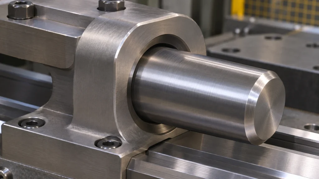
Record the contact geometry and consequence of failure as well. Broad bearing contact, a sharp edge, a small guide land, and a threaded engagement create different local conditions. If wear changes a sealing diameter or release force, define the functional limit rather than relying on “galling resistant” as an acceptance criterion. For material context, compare the proposed grade with the site’s metal materials overview, then resolve the pair-specific requirement on the drawing.
Why the alloy can help—and what it cannot guarantee
Carpenter describes Gall-Tough PLUS, its Nitronic 60 product, as a high-silicon, high-manganese, nitrogen-strengthened austenitic stainless alloy with resistance to self-mated galling and metal-to-metal wear. That manufacturer statement explains why engineers consider the grade for relative motion under load. It does not establish a universal coefficient of friction, a life prediction, or immunity to adhesive wear in every mating combination.
Counterface hardness and finish, alignment, contact pressure, surface damage, debris, lubrication, temperature, and corrosion exposure can change the result. A hard burr or a misaligned edge can concentrate load; roughness can disrupt a thin lubricant film; a material pair that behaves well in one test can behave differently after a coating, cleaning, or heat history changes. Treat alloy selection as one control in a tribological design, not as the whole design.
| Drawing or RFQ input | Why it affects the decision | What to define |
|---|---|---|
| Mating material and treatment | Sets the opposing surface and possible material transfer behavior | Grade, coating, hardness range if controlled, and which part moves |
| Motion and load | Distinguishes sliding, oscillation, impact, and static contact | Direction, frequency or duty cycle, load boundary, and contact region |
| Surface condition | Finish, edge condition, and damage can dominate local contact | Functional finish zones, edge break, and inspection method |
| Environment | Lubricant, temperature, and corrosive media change service behavior | Named medium and operating range, not “corrosion resistant” alone |
Turn the duty into drawing requirements
Separate material identity from functional acceptance. Call out the governing material specification and product form, and require traceability appropriate to the part’s risk. Then locate the surface that performs the sliding or bearing function and specify the dimensional, geometric, and finish controls that protect it. A general surface-finish note across every face may add inspection burden without controlling the working interface.
Use a section view or detail when the contact land, edge radius, or relief is not clear in the primary views. State whether a coating or post-machining treatment is allowed, because it can alter fit and the contacting surface. If qualification testing is needed, define the counterface, load, motion, lubrication, environment, duration, and failure threshold. A bare request for “anti-galling material” leaves too many variables unresolved.
Protect the functional surface during machining
The machining plan should preserve geometry and avoid avoidable surface damage: establish datums that relate to the assembled contact, support the part near the critical feature, and keep burr removal from rounding a controlled edge or narrowing a land. The exact tool and cutting conditions depend on stock condition, machine rigidity, feature geometry, and the shop’s validated process; generic values should not be copied onto a drawing.
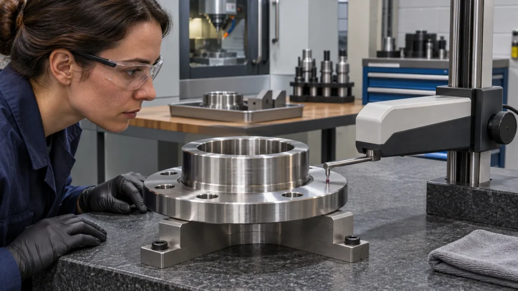
Where the part is turned, milling or turning sequence should leave a clean, inspectable contact surface and avoid handling marks before final measurement. Specify whether finish is measured before or after any permitted treatment, and identify the measurement direction where that matters. The site’s CNC turning capability page and CNC milling page describe the relevant process categories; they are not a claim that a particular tribology test is included.
Accept the part as a system
For a noncritical guide, dimensional inspection and material traceability may be sufficient if the design owner has already qualified the pair. A safety-related, sealing, or high-cycle contact may require a representative test or documented engineering approval. Do not infer service performance from a certificate that only confirms chemistry and tensile properties.
When a field problem occurs, preserve the failed surfaces and compare both members. Look for transferred material, scoring direction, localized pickup, edge impact, lubricant starvation, and alignment evidence. This failure review can distinguish an alloy issue from a geometry, assembly, contamination, or lubrication issue—and avoids changing material while the initiating cause remains.
RFQ questions for a Nitronic 60 part
- Which contact face or feature is functionally critical, and what is its acceptance limit?
- What is the mating material, its surface condition, and the relative motion?
- Are lubricant, coating, cleaning, or heat exposure controlled?
- Which stock form, material specification, condition, and traceability are required?
- Is acceptance based on drawing dimensions, surface measurement, a qualification test, or a combination?
A well-defined contact duty lets the designer decide whether Nitronic 60 is appropriate and lets the manufacturer machine and inspect the surfaces that matter. The grade name is the beginning of the specification, not its conclusion.