
For a CNC-milled pocket, specify the largest internal corner radius the assembly can accept; a larger radius can leave room for a larger, stiffer cutter, while a tight radius may require a smaller tool, additional finishing, or a design review. There is no universal minimum radius that fits every pocket. The practical choice depends on the mating part, pocket depth, tool reach, material, tolerance, and the machine route.
A round end mill naturally leaves a rounded vertical corner. If the pocket must receive a square mating feature, the radius is a functional interface, not a cosmetic detail. If the corner is nonfunctional, a larger radius can often simplify access and reduce the need for small tools. Before putting a number on the drawing, separate the wall corner from the floor transition and verify which one controls fit or sealing.
Two different radii are often confused
The vertical internal corner in a milled pocket is the radius in plan view, where two pocket walls meet. A flat end mill with diameter D has a cutting radius of D/2; the vertical corner it produces cannot be sharper than that tool radius without another operation or geometry. A smaller cutter can reach a tighter corner, but the tool’s reach, stiffness, and engagement still need to suit the pocket.
The radius where the pocket wall meets the floor is a different feature. A square end mill may leave a small floor fillet determined by its bottom corner geometry; a ball-nose or a dedicated radius tool creates a different transition. If the drawing only says “internal radius,” a supplier may not know whether it means the vertical corner, the wall-to-floor fillet, or both. Show the feature in a section or detail when that distinction affects function.
The cutter sets a geometric limit, not a universal design rule
Geometry gives the first check: a 10 mm end mill has a nominal 5 mm cutting radius in the pocket corner. That relationship does not mean every 5 mm pocket radius is easy or economical. A toolpath entering the corner changes radial engagement; at high engagement, cutting forces and vibration risk can rise. A radius slightly larger than the planned cutter radius can give the toolpath room to flow through the corner. The best amount of clearance depends on the cutter, material, depth, and CAM strategy.
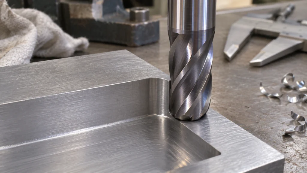
When the design insists on a small radius, the shop may use a smaller end mill for the whole feature or clear the bulk with a larger tool and finish the corners separately. The second route adds tool changes and may leave a visible transition between passes. Long-reach tools can deflect, chatter, wear, or lose surface quality more readily than a short, robust cutter. A tight radius therefore affects more than the final two-dimensional shape: it can influence cycle time, tool life, finish, and inspection effort.
Do not copy a fixed “minimum corner radius” from a generic chart as a guaranteed shop capability. Tool diameter, flute length, holder clearance, workpiece material, machine rigidity, and part quantity all matter. The site’s CNC milling capability page gives the process context; the exact radius still needs to be checked against the actual geometry and acceptance requirements.
Let the mating feature determine the corner
For a pocket that locates a block, insert, seal, or sensor, begin with the mating geometry. Does the part need full contact at the corner, or does it locate from the pocket walls and bottom? Could a small clearance or a relieved corner preserve the function while allowing a larger cutter? A relief such as a dogbone can create clearance for a square mating part, but it removes material and may weaken a wall, intersect a seal land, trap debris, or complicate inspection. It needs engineering approval when it changes a functional section.
If the corner is not an interface, avoid specifying a tiny radius just because the CAD model shows a sharp edge. CAD is exact; a milled pocket is produced by a rotating tool. State the intended radius where it matters and allow a practical radius elsewhere. For a sealing groove, bearing seat, or high-stress corner, derive the geometry from the mating component and design requirement rather than from a generic manufacturing suggestion.
Pocket depth changes the cost of a tight radius
A deep pocket asks the cutter to reach farther below the holder. If the internal radius also forces a small diameter, the tool becomes more slender relative to its reach. That combination can reduce rigidity and increase deflection, chatter, and sensitivity to tool runout. A shallow pocket may tolerate a small cutter that would be unsuitable at a greater depth. Material and wall support change the answer again.
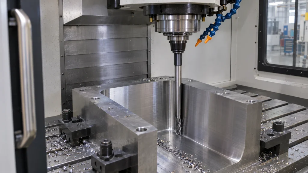
Review radius, depth, wall thickness, access direction, and the surface requirement together. A larger corner may permit a larger tool and a more stable path, but the pocket’s other constraints can still set the limiting feature. Where a small radius is essential, mark it as critical and discuss the route before freezing the part design. The site’s design guides provide a broader DFM starting point, while the part drawing controls its dimensions.
How to call out the requirement clearly
- Dimension the vertical pocket corner and wall-to-floor transition separately when both matter.
- Identify the mating component, seal, or contact feature that sets the functional limit.
- Use a detail view for a tight corner, relief, or local exception to a general radius note.
- State whether unspecified internal corners may use a supplier-selected radius within a defined boundary.
- Set tolerance and inspection method on the critical radius; do not apply a tight tolerance to every nonfunctional edge.
- Review deep pockets and long tool reach before release, especially when a small corner radius is mandatory.
A useful radius is the one that preserves assembly function and can be produced with a stable, inspectable route. If the corner is functional, define it. If it is not, give the machinist enough room to use a practical cutter and keep the drawing focused on the surfaces that control the part.