
Molybdenum can be machined with conventional processes, but a steel-based recipe is a poor starting assumption. The useful controls are the material form and condition, cutting-edge sharpness, rigid support, chip evacuation, and a finishing plan that protects the required surface. Molybdenum’s room-temperature ductility and tendency to chip can make corners, thin sections, and interrupted cuts less forgiving than a simple “refractory metal” label suggests. Confirm the exact grade and product form before selecting a route; data for pure molybdenum should not be transferred automatically to a molybdenum alloy.
For a CNC part, treat the job as two linked tasks: remove stock without initiating edge or surface damage, then verify that the finished geometry and surface meet the drawing after the part is released from its fixture.
The stock form sets the first constraint
“Molybdenum” may refer to commercially pure material or an alloy, and supply can arrive as bar, plate, sheet, or a near-net form. These are not interchangeable machining conditions. Ask for the grade, product specification, manufacturing route, condition, dimensions, and material certification. Grain direction or working history may matter for a feature that loads across a thin section or has a sharp internal transition.
Before programming, inspect the blank for actual geometry and available cleanup allowance. A saw-cut end, rolled surface, or pre-existing corner defect can change where the first stable cut begins. The machining sequence should not force a thin edge to support a heavy roughing load simply because the nominal model leaves material there. The metal materials overview is a starting point for comparing material families; the supplier’s certificate and drawing govern the specific stock.
Read chips and edges as process feedback
Industry guidance from the International Molybdenum Association notes that sharp tools and rigid, backlash-free setups are important because a dull edge can tear rather than cut cleanly; chips and dust can also abrade cutting edges. That mechanism gives a practical diagnostic: a deteriorating finish, unstable cutting sound, chipped edge, or changing load should prompt a check of tool condition, support, chip evacuation, and material condition before a parameter change is treated as the answer.
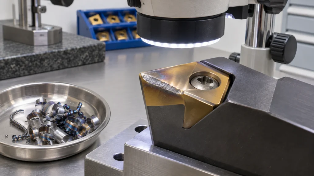
Do not judge a process from chip color alone. Record the actual tool, engagement, stock condition, coolant practice, and feature location with the observed defect. If edge chipping clusters at corners or at breakthrough, the cause may be interrupted engagement or insufficient support rather than a global speed problem. Keep the machine enclosure and chip-management practice appropriate to the material and coolant; avoid sweeping fine metal debris into unrelated equipment or work areas.
| Observed symptom | Potential process question | Useful check |
|---|---|---|
| Edge chips at a corner | Is the cut interrupted or is the feature unsupported? | Tool engagement, stock allowance, and local fixturing |
| Rough or torn surface | Has the cutting edge dulled or rubbed? | Tool edge condition, load trend, and finish pass setup |
| Changing dimensions after release | Was the blank constrained or stressed during cutting? | Datum strategy, clamping sequence, and free-state measurement |
| Rapid edge wear | Are chips abrading the edge or recutting? | Chip path, evacuation, coolant delivery, and tool inspection |
Choose a route that protects brittle features
Roughing should prioritize stable support and manageable engagement. Leave enough stock to produce a continuous finish cut, but do not preserve a thin web that will flex or chip under the later operation. For a pocketed plate, consider machining opposing faces in a sequence that maintains stiffness; for a slender turned feature, keep the unsupported length short and plan where the part is supported as the geometry changes.
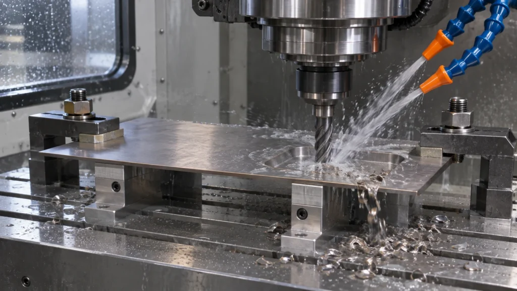
Tool geometry and cutting data should be selected from the actual alloy, tool supplier’s recommendations, and a controlled first-off trial. Published guidance offers starting context, not guaranteed speeds and feeds for every machine, insert, section, or tolerance. Avoid making several changes at once: a stable process window depends on knowing whether edge life, surface integrity, or dimensional movement is the limiting factor.
Finish the surface without hiding damage
Separate dimensional finishing from any abrasive or polishing operation. If grinding is used, identify which faces and datums must remain protected and define the final measurement stage. A bright surface is not proof of an undamaged subsurface, and a visual blend can obscure a local chip or tear at a corner. For a critical component, the drawing owner should state whether inspection is visual, dimensional, surface-finish based, or requires another approved method.
The site’s CNC milling page and precision grinding page describe relevant process categories. They do not imply that every molybdenum form or specialized inspection method is available; confirm material and acceptance requirements during quotation.
Inspect after the part is free
Measure critical dimensions after the part has been released from the fixture and allowed to reach the specified inspection condition. For thin sections, asymmetric removal, or narrow datum pads, compare measurements while clamped with free-state results during process development. The drawing should define the datum reference and any required geometric control so that two inspectors do not choose different setups.
Record material heat/lot identification, stock condition, tool and route revisions where required by the quality plan. If a crack-like indication or chipped feature appears, stop and disposition it against the engineering acceptance criteria; do not “polish it out” without approval. The quality page provides the site’s quality-system context, while part-specific acceptance remains on the approved drawing and order documents.
What to put in the RFQ
- Exact molybdenum grade, product form, condition, and material certificate requirements.
- Critical edges, thin sections, datum scheme, finish zones, and inspection stage.
- Whether grinding, polishing, or a specific coolant/material-control restriction is required.
- Quantity, revision, and any first-article or traceability documentation.
These details make the process discussion concrete. A generic request for a “molybdenum machined part” leaves the highest-risk variables—the stock and the acceptance boundary—unresolved.