
Short answer: treat a kingpin as a coupling interface, not simply as a turned shaft. For a fifth-wheel trailer kingpin, the shank, shoulder, grooves, mounting face, and any attachment features must be machined and inspected from datums that reflect how the part seats and engages. The drawing and applicable product standard define the actual dimensions and acceptance limits; a generic machining recipe cannot establish interchangeability or service safety.
This guide focuses on the upper-coupler kingpin used with a commercial trailer fifth wheel. It does not combine that part with a steering-axle kingpin, a tow hitch pin, or other pins that share the name but have different interfaces and loads.
Define the kingpin and its governing interface
The word kingpin is used for more than one vehicle component. In this article it means the trailer-side pin that engages a tractor’s fifth wheel through the upper coupler. Steering-system kingpins are pivot components in a wheel-end assembly; tow pins can refer to different hitch or drawbar parts. Their functions, retention details, standards, and inspection plans are not interchangeable. A drawing should identify the component family, interface, and governing specification before a machinist decides how to hold or measure it.
For this trailer application, the relevant standards depend on the coupling design and nominal size. SAE J700 addresses upper-coupler kingpins for commercial trailers and semitrailers, while ISO 4086 covers a defined 90 mm semi-trailer fifth-wheel kingpin and its mounting/interchangeability characteristics. Those references are not blanket approval for every kingpin design. Confirm the standard edition required by the customer, the specified kingpin type, and any OEM drawing notes before quoting or programming.
The machining supplier’s job is to produce the features assigned in the part drawing and maintain traceability to the agreed material and process scope. That does not by itself certify the complete coupling, weld, trailer structure, or vehicle for a service load. Keep design approval, material certification, heat-treatment records, weld procedure, and product-level qualification with the responsible parties named in the purchase specification.
Read the shank, shoulder, and mounting geometry as a system
The cylindrical shank is only one part of the functional interface. Its diameter and form relate to the fifth-wheel locking mechanism; the shoulder and transition establish where the mating surfaces contact; grooves or reliefs may provide clearance or retention; and the flange or mounting face locates the pin relative to the coupler plate. A part can meet an isolated diameter callout and still assemble poorly if the shoulder face is not square to the axis or if the mounting datum is inconsistent with the shank datum.
Begin the process review by identifying a datum scheme that mirrors assembly. If the drawing establishes the pin axis from a cylindrical feature, use that axis to control the relationship of the shoulder, end face, and any concentric details. If the mounting face is the primary seat, define how that face is held and how the pin axis is recovered after a setup change. Avoid treating every surface as an independent dimension when the assembly depends on coaxiality, perpendicularity, or a controlled contact band.
Transitions deserve particular attention. A generous-looking radius may interfere with a mating throat or seating surface; a sharp corner may be prohibited by the print or create a difficult inspection point. The drawing should state the required radius, chamfer, undercut, or relief where it affects fit. Do not infer a standard profile from a product photo or substitute a convenient tool radius without engineering approval.
Choose a CNC route from the supplied stock and features
Rotational features such as the shank, shoulder, end face, and concentric grooves are natural turning operations. A practical sequence may establish the principal axis, rough the main diameters, leave material for the specified finish operation, and complete critical surfaces in a setup that preserves their relationship. Actual order depends on whether the supplier receives bar, a preformed blank, or another approved stock form. Do not assume a forging or claim that forging, welding, or forming is part of a CNC machining quote unless it is explicitly included.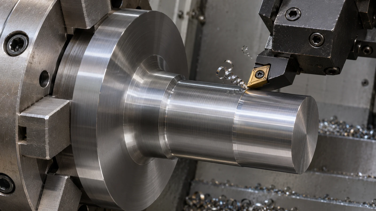
Features that do not share the main axis—bolt holes, flats, keying details, or cross-holes on a particular design—may require milling or drilling after turning. The choice between separate turning and milling setups and a combined turn-mill route depends on feature access, quantity, equipment, and the datum-transfer risk. For a simple turned configuration, review the shop’s standard CNC turning scope; a multi-feature part may call for a different process review.
Setup strategy should reduce the chance that a finished shank is re-clamped on a less reliable surface. Soft jaws, a suitable collet, a supported center, or a dedicated fixture may be considered where the actual geometry and machine permit. The important question is not which fixture sounds most precise; it is which contact surfaces locate the part without distorting it and allow the critical features to be cut relative to a repeatable axis. Long overhang, interrupted cuts, and a small clamping area can change the answer.
Where threads are part of the design, specify the thread standard, class, effective length, runout or relief, and the inspection method. The threading feature is not necessarily the same as the coupling shank and should not be used as an assumed datum unless the drawing says so. If a nonstandard thread is called out, the site’s custom thread machining information is relevant to the thread scope, but the mating hardware and acceptance gauge still need to be defined by the customer.
Coordinate material condition and downstream treatment
Do not choose a steel grade from the word “kingpin” alone. The material, product form, condition, and any heat-treatment requirement should come from the drawing or approved specification. Different kingpin families can use different alloys and treatment routes. The material producer’s data and the product owner’s requirements control; a grade listed on a general material page is not a recommendation that it is suitable for a specific coupling.
Heat treatment can change dimensions and may change how a part responds to finishing. If the agreed route includes treatment between machining operations, identify which surfaces are rough-machined, which features need allowance, which datums must be recovered, and which dimensions are accepted after the final process. Do not insert a universal stock allowance or compensation value. It depends on the part, material condition, heat-treatment process, geometry, and documented prior results.
For context on the range of steel families available for CNC work, see the site’s high-strength materials overview. It should be used as a material-family reference only. A kingpin’s service requirements, standard, and approved material designation take precedence over a broad category label.
Inspect the relationships that control engagement
Inspection should follow the drawing’s functional datums and acceptance notes. A diameter measurement at one cross-section will not show whether a long shank is tapered, lobed, or bent. Depending on the print, the plan may need checks at multiple axial positions, a method for evaluating roundness or cylindricity, and a runout check relative to the established axis. The required instruments and sampling plan should be agreed before production rather than invented after a fit problem appears.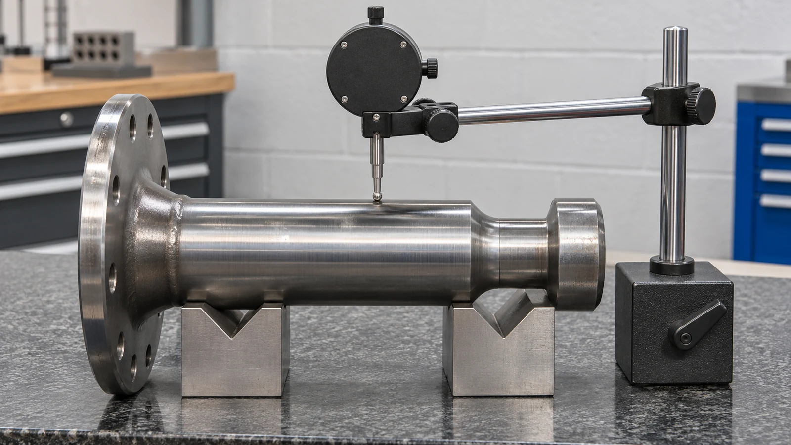
Check the shoulder face and mounting interface in relation to the shank datum, not just as isolated flatness or thickness values. If there is a bolt pattern, verify its position from the design datums and confirm the hole features do not compromise the intended mounting contact. Threads, grooves, radii, and edge breaks need their own explicit acceptance criteria when they affect installation or retention. Record the measurement method and the condition in which dimensions are accepted, especially when treatment or coating follows machining.
Surface finish is similarly functional. A contact surface may have a specified texture or finish direction, while a non-contact relief may have different requirements. “Polished” is not a measurable acceptance criterion by itself. Use the drawing’s texture callout and identify the measurement direction and location if those details matter. A supplier should not promise a service-life or wear result from a finish value alone; mating-part condition, lubrication, alignment, load, and maintenance also influence behavior.
Illustrative review: a bolt-in kingpin with a mounting plate
Consider a hypothetical drawing for a bolt-in fifth-wheel kingpin assembly. The pin has a turned shank and shoulder, a mounting face, and a bolt pattern on a separate plate. This is an illustrative planning example, not a customer job or a claim about a tested JUCHENG product. The design authority has specified the material and the assembly acceptance requirements.
The first review would separate the pin’s rotational datum from the plate’s mounting datum and ask how they are related in the completed assembly. If the pin and plate are supplied as separate pieces, the machining scope must make clear whether the supplier only machines them, also assembles them, or receives a completed welded assembly for finish work. These are different scopes. A dimensional report for the loose pin cannot substitute for verification of the final assembly relationship.
Next, the team would define which surfaces are critical after any specified treatment and how the pin will be located for final inspection. A useful route might turn the shank and shoulder from a stable reference, then use a controlled fixture for plate features, followed by a datum-based final check. But that sequence is only a candidate: the drawing, stock form, equipment, and process records determine whether it is suitable. If the measured axis shifts after a treatment or join operation, the process owner needs an approved recovery step—not an undocumented adjustment to the nominal dimensions.
This review catches common communication gaps before they become scrap or rework: a material grade without condition, a bolt pattern without a datum, a shank diameter without a form requirement, a finish callout without a measurement location, or an acceptance standard whose revision is not identified. None can be safely resolved by guessing from the part name.
What to include in a machining request
For a kingpin-related RFQ, provide the current drawing revision and CAD model, part family, quantity, specified material and condition, and the standard or OEM specification that governs the interface. Mark the shank, shoulder, mounting face, hole pattern, grooves, threads, and any critical surface texture or edge details. State whether stock is supplied and whether heat treatment, coating, welding, assembly, or inspection records are included in the requested scope.
Separate required characteristics from preferences. Identify the datums and the dimensions that control fit; specify the condition in which final acceptance occurs; and list the records needed with each lot, such as material certificates or dimensional reports, when contractually required. If a safety or regulatory approval applies, name the responsible design authority and the required qualification evidence. The machinist can review manufacturability and quote the defined machining scope, but should not infer product certification or vehicle-level approval from a drawing title.
A clear request lets the supplier assess access, setup count, datum transfer, treatment sequence, inspection effort, and risk before committing. It also makes alternatives discussable: for example, whether a feature can be moved to a more accessible setup or whether an inspection datum needs clarification. Any design change remains subject to customer approval and the applicable product requirements.
Kingpin machining questions
Is a trailer kingpin the same as a steering kingpin?
No. A trailer fifth-wheel kingpin engages the tractor’s coupling, while a steering kingpin belongs to a wheel-end pivot system. They have different geometries, mating parts, and governing requirements, so keep their machining and inspection discussions separate.
Can every kingpin be made from the same steel grade?
No. Use the material and condition specified for the particular design. The component name alone does not establish alloy, heat treatment, hardness, or suitability for a coupling application.
Does CNC turning alone define the final kingpin accuracy?
No. Turning can create the principal rotational features, but a design may also need milling, drilling, threading, treatment, or assembly operations. Final acceptance depends on the drawing’s datum relationships and the condition in which the part is inspected.
Does machining a part to SAE J700 mean the complete assembly is certified?
No. A machining supplier must work to the agreed drawing and applicable standard scope. Product qualification, weld procedures, assembly acceptance, and vehicle-level approval are separate responsibilities that require their own evidence.
In short, plan kingpin machining around the actual fifth-wheel interface: establish the functional axis, preserve the shank-to-shoulder and mounting relationships, coordinate the material and downstream process condition, and inspect the drawing-defined features. Confirm the part family and acceptance basis before treating a kingpin as a routine turned pin.