
Short answer: Incoloy 825 machining begins with the mill condition and the operation list, not with a copied parameter table. Special Metals states that standard machining operations can be performed and that the alloy normally has optimum machining characteristics in the annealed temper. Confirm the supplied condition and specification, then qualify the tool, engagement, coolant, and finish plan for the actual feature.
INCOLOY alloy 825 is commonly designated UNS N08825. The producer’s technical bulletin is the primary source for grade-specific information; a general nickel-alloy recommendation should not override the material certificate, drawing, or current toolmaker data.
Start with the supplied condition
Before choosing a route, match the alloy designation, product form, heat-treatment condition, and certificate to the purchase order. The same grade can arrive in different forms and conditions, and these affect how a specific job behaves. Special Metals’ bulletin says the annealed temper normally offers optimum machining characteristics, but that statement is not permission to substitute condition or assume every part is annealed. If the documentation conflicts, resolve it before machining.
Keep the scope of the decision clear. A corrosion-resistant material category or a high-temperature materials overview can provide context, but neither replaces the customer’s service specification. The site’s high-temperature materials page is a family overview; this guide addresses the machining sequence for Incoloy 825 components.
Prevent rubbing without forcing an unqualified cut
Nickel-alloy machining is sensitive to how the cutting edge meets the stock. A tool that dwells, rubs, or repeatedly crosses a work-hardened surface may lose edge life and shift the dimension before the operator sees a dramatic finish change. Maintain a stable engagement and avoid unnecessary pauses at the cut. Select insert geometry, edge preparation, and coolant delivery using the toolmaker’s guidance for the operation and machine.
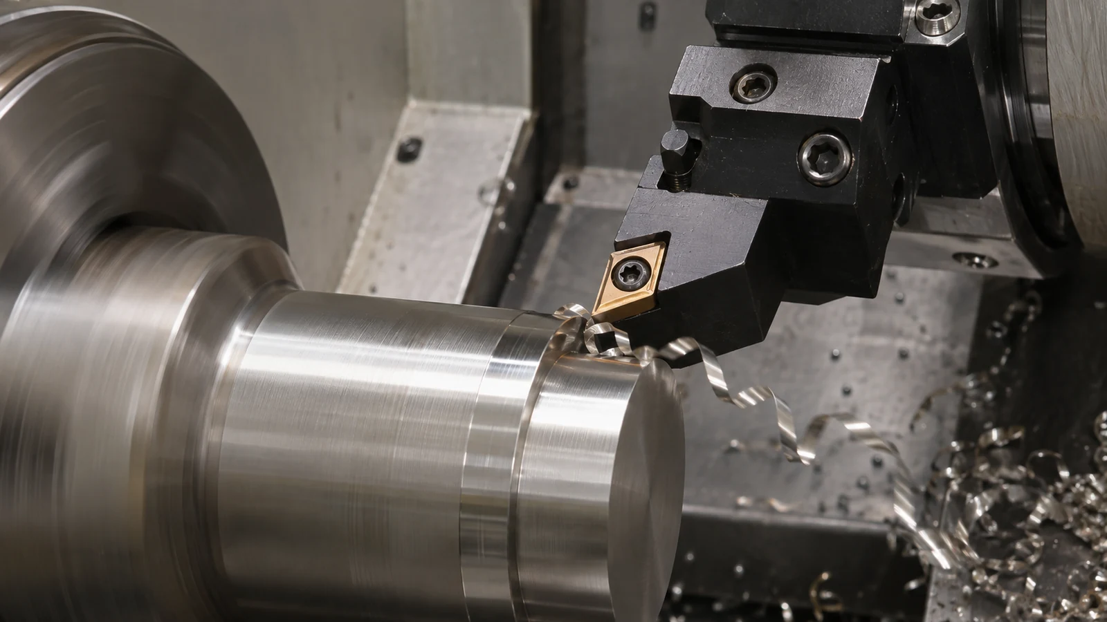 “Keep the tool cutting” does not mean maximize feed or depth. A thin wall, small bore, or interrupted surface may need a different engagement from a rigid turning operation. Establish an operation-specific starting point on representative stock, monitor chip shape and edge wear, and adjust one variable at a time. Published data is a reference only when its workpiece condition, tool grade, rigidity, coolant, and engagement resemble the job.
On a milling operation, the CNC milling capability page gives process context. For a turned journal or concentric bore, select a setup that preserves the axis reference through roughing and finishing rather than treating each surface independently.
Plan long features, bores, and chip paths separately
A long slender shaft, a deep bore, and a pocketed housing each create different constraints. Long parts need support near the cutting zone and a check on deflection after clamping. A bore needs a tool and chip path that can reach the bottom without packing chips against a finished wall. Pockets need a way to evacuate chips rather than repeatedly recutting them. Workholding, tool overhang, and access should be decided from the drawing before the program is finalized.
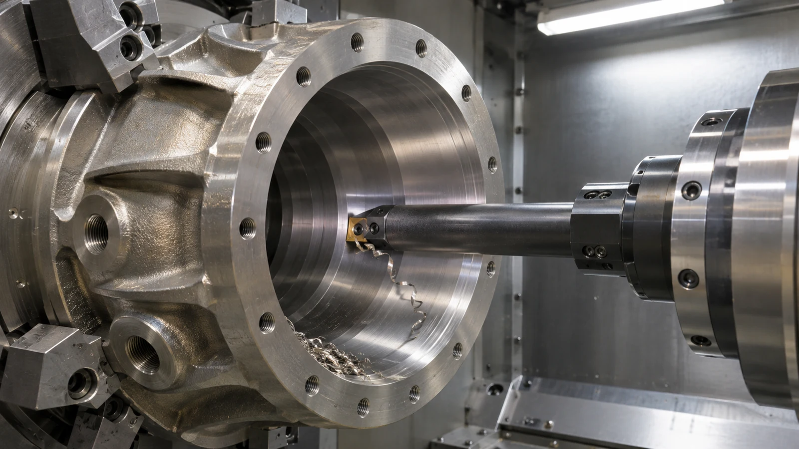 Separate roughing from finishing when heat, cutting forces, or stock release could move a critical surface. If the part is flipped, establish how the primary datum is recovered and how coaxiality or face relationships are verified afterward. This is especially useful where the component combines turned and milled features. The best route is the one that maintains the required geometric relationships with a measurable process, not simply the one with the fewest operations.
Make finish and inspection part of the route
Surface finish should be specified and inspected only where the drawing or function requires it. A sealing face, bearing interface, and nonfunctional exterior do not necessarily need the same finish. Tool wear, vibration, chip recutting, and measurement condition can all affect the observed result. Define the inspection method and sampling plan for the feature rather than assuming a visual check can establish a numerical finish.
For Incoloy 825 machining, preserve the link between material condition, operation, and final acceptance. Record the stock identity, critical setup references, and the measurements that verify the drawing. Avoid presenting a single speed, feed, or tolerance as universal: the correct values depend on the tool system, machine, feature geometry, and customer requirement.
Hypothetical route review: a probe housing with a deep bore
Illustrative scenario, not a JUCHENG customer case: suppose an instrument probe housing is specified in Incoloy 825, with a long central bore, a flange face, and a radial port. Its service conditions and material selection are defined elsewhere in the engineering package. The machining challenge is to preserve the bore-to-face relationship while providing a clear chip path and access for inspection.
First check the supplied material condition against the certificate and drawing. Then review whether the bore is rough-machined before the flange face is finished, or whether the face should be established earlier as a datum. The answer depends on blank geometry and workholding; it should be judged by how the critical axis can be recreated, not by a universal “face first” rule. A long boring tool may deflect, while trapped chips can score a wall or obscure a developing tool problem. The route needs access for chip evacuation and an inspection method that can reach the specified depth.
For the radial port, define its relationship to the bore and flange before selecting a second setup. A rotary or multi-axis route may reduce repositioning, but only if the actual machine, fixture, and inspection plan support it. Otherwise, establish a repeatable transfer datum and verify port location after reorientation. Do not describe a machine configuration as a guaranteed capability until the job is reviewed.
At first article, inspect the bore, flange, port position, and specified finish separately. If the bore is undersize, inspect tool condition and measurement method before applying a blanket offset; a long tool, chip packing, and probe access can produce different causes. Record which condition and operation produced each accepted feature so a later adjustment does not obscure the original process evidence.
Match the method to the feature, not the alloy label
| Feature | Planning issue | Useful drawing or inspection detail |
|---|---|---|
| Long bore | Tool reach, stiffness, chip removal, and measurement access interact. | Depth, diameter, straightness or position requirement, datum, and inspection access. |
| Flange face | Clamping can distort a thin flange or affect the face-to-bore relationship. | Seating datum, specified flatness or finish, and support state for inspection. |
| Radial port | A second setup may disturb angular or positional alignment with the main bore. | Position reference, clocking datum, and how the feature is verified after reorientation. |
The table does not prescribe a machine or number of setups. It helps the designer and supplier identify what must be measured and which access or workholding questions need answers before the process is quoted.
Incoloy 825 machining questions
What condition is generally preferred for machining Incoloy 825?
Special Metals states that the alloy normally has optimum machining characteristics in the annealed temper. Confirm the supplied condition and governing material specification; do not assume or change it.
How should a deep bore be planned?
Plan tool access, rigidity, chip evacuation, and inspection reach together. A bore that can be cut but cannot be measured or cleared of chips is not a complete process plan.
Can data for Inconel 718 be used on Incoloy 825?
Do not transfer it as a production recipe. Use current toolmaker data and qualify the actual insert, workpiece condition, machine, coolant, and engagement.
A dependable Incoloy 825 machining route connects producer condition guidance with stable engagement, chip removal, and inspection access; any process setting must still be qualified on the specified part and operation.