
Short answer: Alloy 20 machining should be planned around the features that preserve the part’s intended function: sealing faces, bores, thin walls, and datum relationships. First confirm the ordered grade and product condition from the drawing and material records. Then choose a stable machining sequence and inspect the geometry that the assembly or process actually depends on. A material designation alone does not establish corrosion suitability for every service environment.
Alloy 20 is commonly identified as UNS N08020, but the purchase specification, product form, and customer requirements remain controlling. This article concerns machining and dimensional control; chemical compatibility must be assessed by the responsible design authority for the actual medium, concentration, temperature, and operating conditions.
Confirm the material before building the route
Start with the drawing revision, UNS designation, product form, and material certificate. Alloy names can be used inconsistently in purchasing conversations, while substitutions or alternate forms may carry different requirements. Record what is actually supplied and resolve discrepancies before cutting. A machinist should not infer a corrosion allowance, heat treatment, or acceptance criterion from the alloy name alone.
Rolled Alloys identifies Alloy 20 as UNS N08020 and describes its product forms and composition on its product page. That is useful material context, not a substitute for the customer’s governing specification. The site’s corrosion-resistant materials overview places the grade within a broader family; this article stays focused on machining and inspection decisions.
Protect functional surfaces through the setup sequence
For a valve body, pump component, or process-equipment fitting, a sealing face may matter more than an attractive general-purpose finish. Define which face establishes the axis, which bore locates an insert, and which holes carry fasteners. Machine a dependable datum first, then reference later operations to that datum wherever the geometry allows. If the part must be repositioned, plan how the reference is recovered instead of relying on an unverified edge or casting feature.
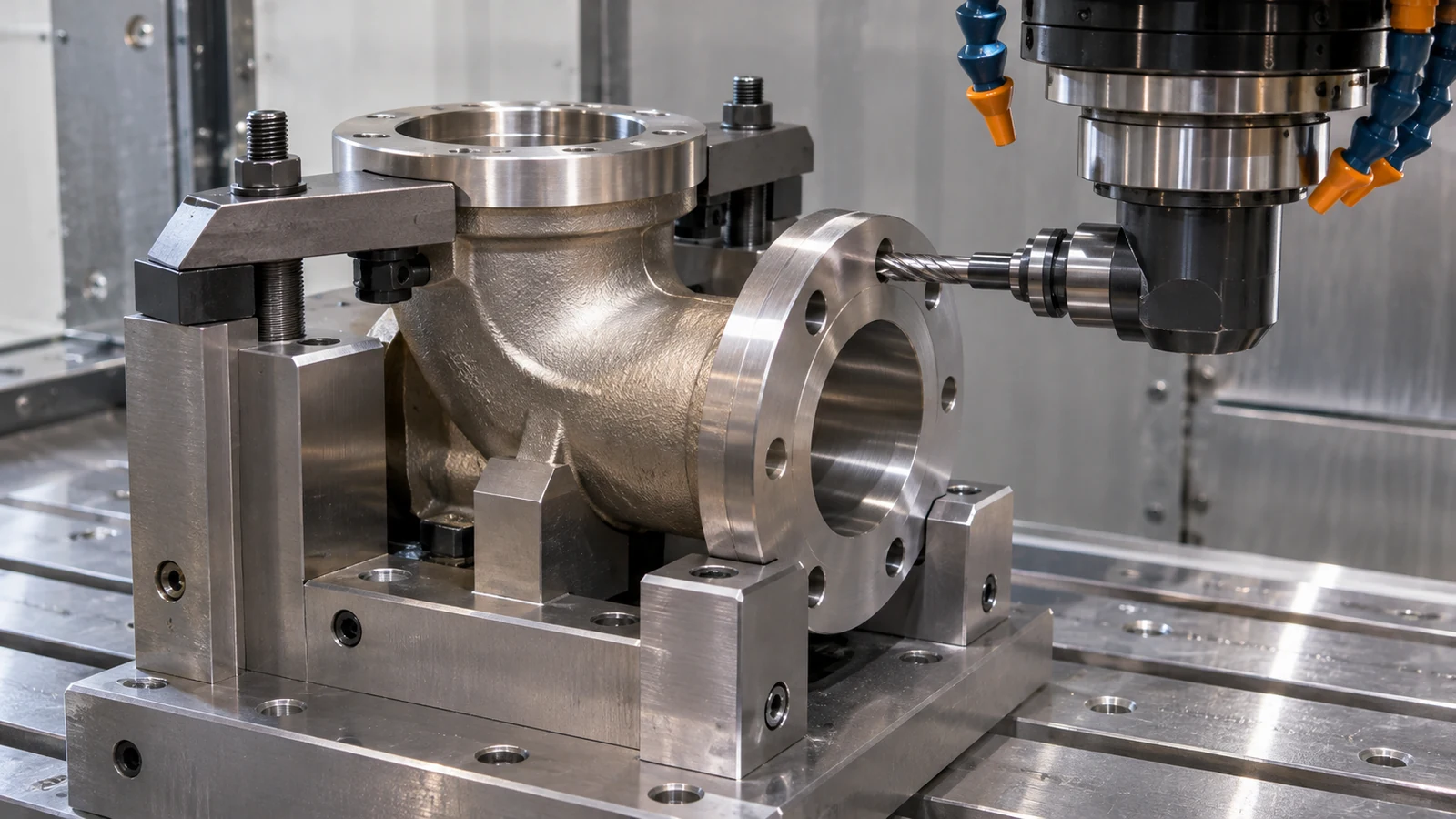
Thin sections and interrupted shapes deserve their own setup review. Clamping pressure can distort a wall or close a split feature; after release, the component may not measure as it did in the fixture. Support the part near the cut, distribute clamping loads, and separate roughing from finishing when the geometry is sensitive. These are process-planning controls, not a promise that every Alloy 20 component needs the same number of setups.
Keep engagement and chip evacuation predictable
Nickel-bearing corrosion-resistant alloys can demand more from a cutting edge than a free-machining steel. A tool that rubs, dwells, or repeatedly cuts a hardened surface layer can accelerate wear and make size drift harder to diagnose. Maintain a purposeful feed through the cut, avoid unnecessary pauses at the wall, and select tool geometry and coolant delivery from the toolmaker’s guidance for the actual machine and feature.
Deep pockets, bores, and narrow slots create different chip-removal problems. A long chip trapped in a bore can mark a finished wall or be recut; a pocket with poor access may retain heat and debris. Adjust the sequence to open chip paths where possible, and inspect the edge and part between operations when the cut is difficult to observe. Do not copy a published speed or feed without confirming the insert, workpiece condition, engagement, rigidity, and coolant arrangement.
The CNC milling capability page describes the site’s milling process range. Whether a specific component is milled, turned, or split across operations depends on its drawing and confirmed production plan.
Good Alloy 20 machining documentation also separates dimensional acceptance from corrosion-service approval. The shop can verify the specified material traceability and geometry; compatibility with a process fluid or cleaning regime must still follow the applicable engineering specification.
Inspect geometry that affects sealing and assembly
Inspection should follow the functional chain, not just the easiest dimensions to measure. For a sealing interface, define the face flatness or finish requirement only as stated by the drawing; for a locating bore, verify diameter and its relationship to the chosen datum. Bolt patterns, threads, and intersecting passages may need positional or functional checks. Use the specified datum reference frame and avoid inventing a tighter shop tolerance than the customer requested.
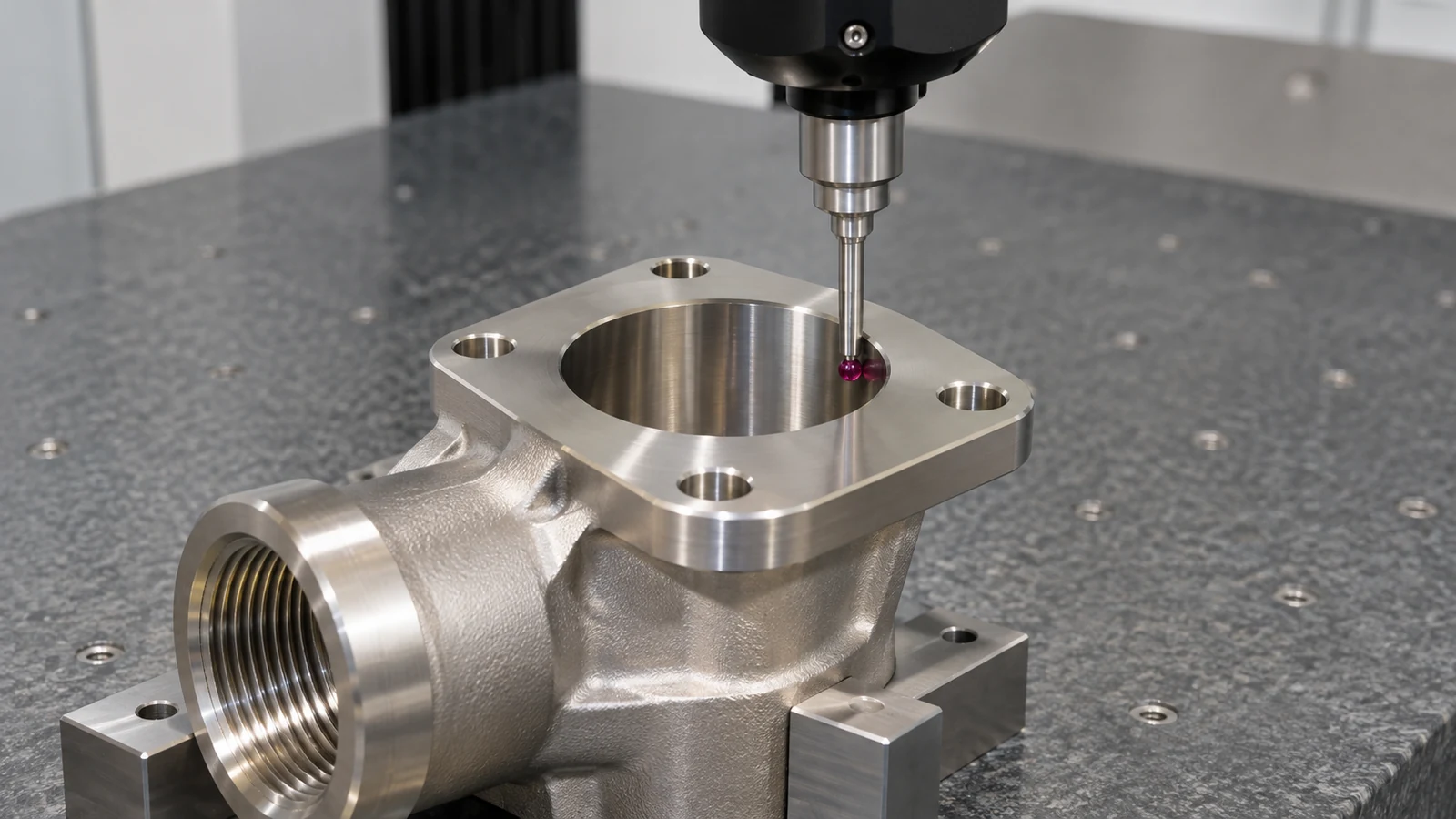
Measure at a stable, documented condition and keep the inspection method appropriate to the feature. A CMM may help establish relationships among bores and faces, while a suitable contact or non-contact method may be more practical for a particular surface. If a finishing operation or later treatment is specified, make clear which dimensions are checked before and after it. The inspection record should show the actual result and method, not imply chemical-service qualification.
Hypothetical drawing review: a pump adapter
Illustrative scenario, not a JUCHENG customer case: a pump adapter is specified as Alloy 20 for a named process fluid, with a central passage, a face seal, and a bolt circle. Material selection and chemical compatibility are owned by the design authority; the machining supplier’s task is to reproduce the drawing-defined interface. A part can meet dimensions yet still be unsuitable if the material specification or service assumptions are wrong.
For the machining review, identify the face that seats against the mating component and use it as the primary reference where practical. Relate the passage axis and bolt pattern to that face, then decide whether one setup can control these features or whether a planned reorientation needs datum recovery. If the face is clamped against uneven support, it may measure correctly in the fixture and lose that condition after release. Inspection should therefore match the specified datum scheme and support state.
During a first-off review, separate three questions: does the certificate match the specified Alloy 20 grade and product form; do the bore, face, and holes meet drawing requirements; and has the responsible engineer approved the material for the actual fluid and operating conditions? These checks are related but one document does not answer all three. The shop can report traceability and measured geometry without implying a corrosion test or service-life guarantee.
This scenario also changes what belongs in the RFQ: the current drawing revision, material specification, sealing-surface notes, datum requirements, and inspection expectations. If surface treatment, cleaning, or passivation is involved, identify it as a separate specified operation and define its effect on critical dimensions.
Keep machining acceptance separate from service qualification
Project teams can prevent a common handoff gap by naming the owner and evidence for each decision:
| Question | Typical responsible function | Evidence that answers it |
|---|---|---|
| Is the supplied stock the specified Alloy 20 product? | Purchasing/material control | Purchase specification, traceability, and material certificate. |
| Does the part meet its dimensional and finish requirements? | Manufacturing and quality | Drawing-based inspection report with datums and method identified. |
| Is the alloy suitable for the actual medium and operating cycle? | Design/materials engineering | Service-specific compatibility assessment and approved specification. |
These records can be coordinated, but they are not interchangeable. A dimensional report cannot certify chemical resistance, and a grade certificate does not establish that a sealing face or passage was machined to the required geometry.
Alloy 20 machining questions
Does machining Alloy 20 confirm suitability for a chemical service?
No. Machining verifies specified geometry and process records. Compatibility depends on the actual medium, concentration, temperature, contaminants, and operating conditions, and must be approved by the responsible engineering authority.
What is Alloy 20’s UNS designation?
Alloy 20 is commonly identified as UNS N08020. Check the purchase specification and material certificate for the exact grade, product form, and revision.
Which features should be inspected first on a fitting?
Start with the drawing’s functional datums, sealing face, passage or locating bore, bolt pattern, and thread requirements. Inspection order should reflect assembly and acceptance rather than measurement convenience.
Can one surface-finish requirement cover every face?
Only when the design specifies that. Sealing, locating, and nonfunctional surfaces can serve different purposes; the drawing should identify where finish limits apply.
A careful Alloy 20 machining plan protects fit and function through material verification, controlled datum strategy, and drawing-based inspection, while keeping chemical-service approval with the responsible engineering authority.