
Short answer: Nimonic 263 machining is easiest to plan when the stock condition, engagement strategy, and tool-wear checks are treated as one process decision. The alloy can work harden and retain heat near the cut, so repeated rubbing, dwell, or a light interrupted skim can make the next pass less predictable. Tool life and surface integrity must be evaluated on the actual form and condition supplied; published test parameters are not transferable shop recipes.
This article focuses on cutting strategy for Nimonic 263 bar, section, and machined components. It is separate from a rough-before-aging guide for Haynes 282: here the central question is how to maintain a stable cut and recognize wear or hardened surface layers while features are being produced.
Identify the product form before choosing the route
“Nimonic 263” is not enough information for a process sheet. Record the UNS designation, product form, heat-treatment condition, section size, certification, and any customer requirements for the delivered state. Special Metals describes the alloy as normally receiving solution treatment and age hardening before service; its published schedules differ by form, and solution-treatment time depends on section thickness. The schedule for extruded or forged bar is not automatically the schedule for hot-rolled sheet or cold-worked product.
That distinction affects machining. A solution-treated stock condition and an aged component present different cutting loads and finish risks. If another processor controls treatment, define the operation boundary and the measurements needed before and after that handoff. The machinist should not infer an aging cycle from a grade name or assume that all material arrives in the same condition.
Keep the tool engaged instead of polishing a hardened track
When a cutter dwells, rubs, or repeatedly follows a shallow path over the same surface, the workpiece can harden locally and increase force on the next engagement. In Nimonic 263 machining, that can show up as changing sound, rising load, accelerated edge wear, burr formation, or a finish that drifts even when the programmed path is unchanged. These are process signals to investigate, not proof of one cause by themselves.
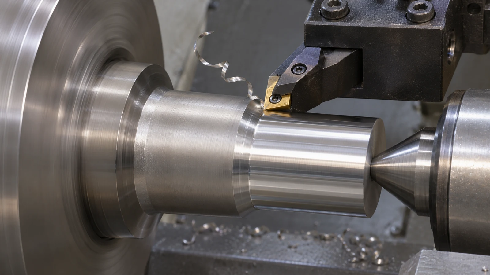 Start with a rigid workholding plan, short tool overhang where possible, predictable entry and exit, and a cut that is deep enough to remove the affected layer rather than repeatedly brushing it. Avoid stopping with the edge in contact. The suitable tool material, edge preparation, coating, coolant approach, and cutting data should be established from a qualified trial for the specific machine, insert, feature, and alloy condition.
Use tool wear as a process-control observation
Do not wait for a broken insert to reveal that the process is unstable. Track a repeatable reference feature, edge-life interval, spindle load trend, burr size, and the surface condition at planned checkpoints. If wear changes sharply between operations, check whether a setup change, interrupted cut, chip recutting, insufficient engagement, or stock-condition change coincides with it.
 Research on Nimonic C-263 reports strong effects from tool system and cutting conditions on wear and cutting temperature. Such experiments explain why selection matters, but their speeds and feeds are tied to their particular tools, machines, and test geometry. Use them as evidence that the process is sensitive—not as a number to paste into a production program.
Route holes, shoulders, and thin sections around access and support
For a part that combines turned journals with milled flats or cross-holes, decide which operations preserve the datum chain and which create unnecessary re-clamping. A turned reference diameter may establish the axis, while milling or drilling creates secondary geometry; the setup must protect the first feature when later cuts apply force. Standard CNC turning can cover suitable cylindrical work, while milling is selected for the non-rotational faces and patterns.
Thin sections and narrow webs need special attention because they can deflect under cutting force and spring back after release. Support the part close to the cut where the geometry permits, distribute material removal, and separate roughing from finishing when the drawing and quantity justify it. If a feature cannot be reached without a long tool or unstable clamp, raise that as a DFM issue rather than hiding the risk in a nominal toolpath.
Read the finished surface before deciding the next pass
A shiny surface is not enough to establish that the cut was healthy. Check the drawing-controlled dimensions, edge condition, burrs, surface texture, and any specified inspection characteristics. If a bore, face, or thin wall is critical after treatment, state the stage at which it is accepted and whether the processor’s movement must be measured before finish machining.
Separate a dimensional correction from a material-integrity investigation. A tool-wear issue may call for an edge-life change; a datum shift may call for a new setup; a surface layer or excessive burr may require engineering review. Do not assume a finish pass can repair every subsurface or process problem.
Illustrative scenario: a ring with a cross-hole and milled flat
Imagine a hypothetical Nimonic 263 ring with a turned bore, an outer journal, one milled flat, and a radial hole. The process plan first turns the datum-related diameters with stable support, then re-clamps from the defined axis to mill the flat and drill the hole. The team logs edge condition after the first pieces and checks whether the radial-hole exit creates a burr that affects assembly.
If the hole tool begins to wear faster after the flat is added, the team reviews chip flow and interrupted engagement before changing the cutting data. If the bore-to-flat relationship shifts after the part is unclamped, it reviews support and datum transfer. This is a hypothetical process review, not a JUCHENG customer case or a claim about a validated production cycle.
What to specify when sourcing Nimonic 263 machining
- Exact designation, UNS or specification, product form, supplied condition, and required certificates.
- Features that define the datum chain, including bores, journals, faces, holes, and thin sections.
- Which dimensions are accepted before and after any heat-treatment or outside-processing step.
- Expected inspection records, surface requirements, burr limits, quantity, and revision control.
- Any feature-access, tool-reach, workholding, or chip-evacuation concern for early DFM review.
Nimonic 263 machining questions
Why can Nimonic 263 machining cause rapid tool wear?
Its strength at temperature, work-hardening tendency, heat concentration near the cut, and tool-work interaction can increase mechanical and thermal stress on the edge. The actual wear pattern depends on material condition, tool system, engagement, geometry, and coolant strategy.
Can a published research cutting speed be used directly?
No. Research values describe a particular test setup and should not be copied into a different machine, insert, part geometry, or stock condition without a controlled qualification.
Should Nimonic 263 be machined before or after aging?
That depends on product form, supplied condition, drawing tolerance, and who owns the treatment. Confirm the approved sequence and finish dimensions with the responsible engineering and purchasing documents.
What should be checked when the finish suddenly worsens?
Check the edge, chip evacuation, tool engagement, clamping, material condition, and whether the part is deflecting. Compare a stable reference feature before changing several process variables at once.