
A turned diameter that grows or shrinks along its length is not automatically a tailstock problem. First confirm that the drawing calls for a straight cylinder, then measure the same diameter at multiple axial positions and at more than one angular orientation. The pattern separates a true taper from ovality, runout, stock movement, or a measurement error. Only after that distinction should you change alignment, support, tooling, or the cutting sequence.
For a long slender shaft, cutting force can bend the workpiece away from the tool. For a short rigid part, a similar diameter trend may point instead to axis alignment, a setup reference, thermal change, or a tool offset. The useful diagnosis comes from changing one condition at a time and checking whether the error follows the part, setup, tool, or machine axis.
Confirm the error before adjusting the machine
Start with the feature definition. A drawing may show a deliberate taper, a relief, a blend, or a diameter transition that looks like a straight-cylinder requirement when only one view is reviewed. Check the dimension, datum references, geometric controls, and section views. If the feature is specified as cylindrical, identify which diameter or form characteristic is failing and how acceptance is measured.
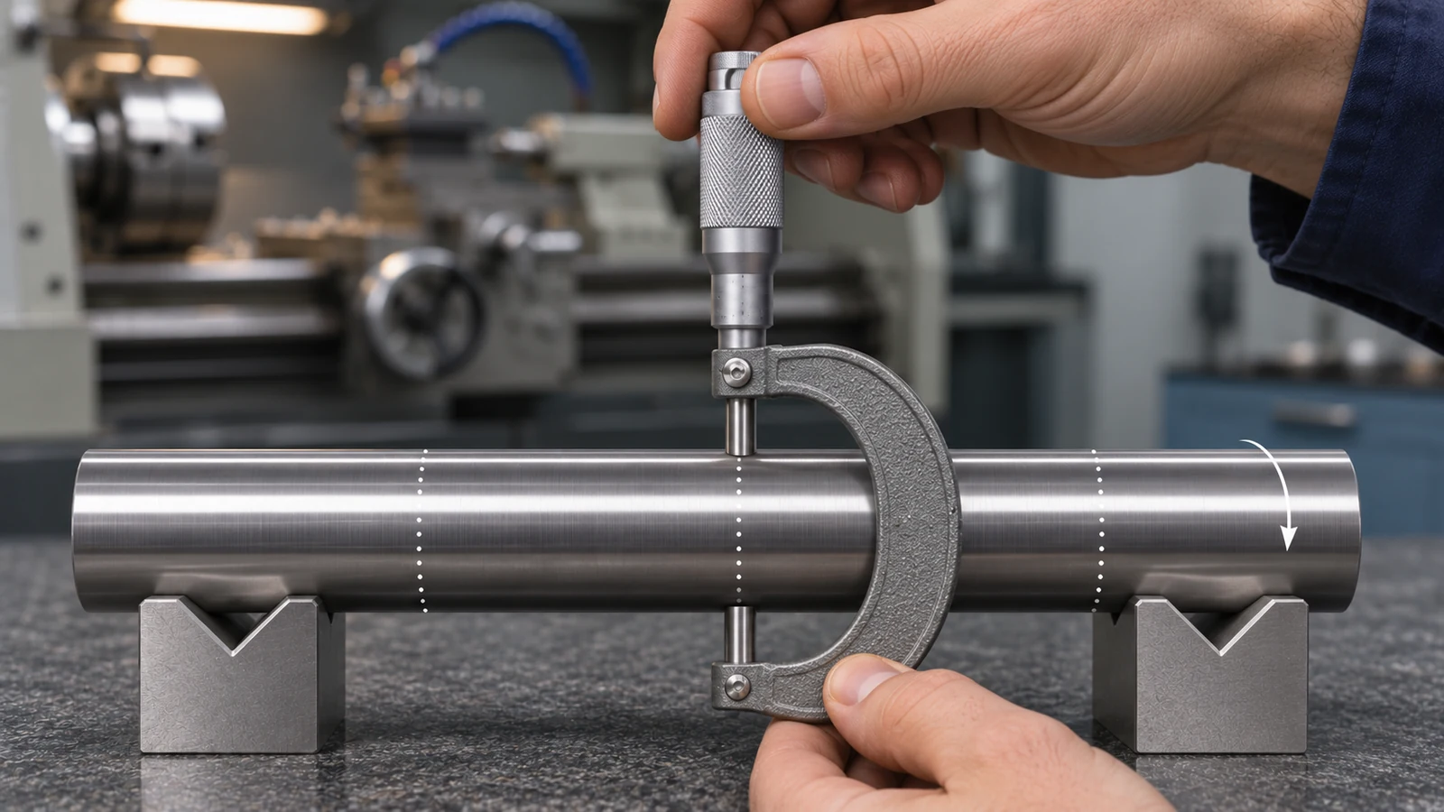
Clean the part and measuring contacts, let the part and instrument reach a stable temperature, and use a suitable calibrated instrument. Record diameters near both ends and at intermediate locations. At each station, rotate the part and take readings at several angular positions. A consistent axial change around the circumference suggests taper; a changing reading with rotation suggests ovality, eccentricity, or runout may also be present.
Read the measurement pattern
A two-point end-to-end comparison can show that a difference exists, but it seldom explains why. A short measurement map is more diagnostic. Record each axial station, angular position, setup, support condition, tool or insert, and whether the measurement was taken before or after unclamping. Keep the data tied to the part datum so a later setup does not reset the reference.
| 관찰된 패턴 | What it can indicate | Next check |
|---|---|---|
| Diameter changes steadily along the axis at several angular positions | Axis alignment, workpiece deflection, tool-path geometry, or thermal drift | Repeat after a controlled cut with one setup variable changed |
| Readings vary mainly as the part rotates | Out-of-round form, eccentricity, chucking distortion, or measurement setup | Measure runout and roundness separately from axial size |
| Error is larger after unclamping | Clamping distortion or residual stress release | Compare in-clamp and free-state measurements using a defined method |
| Error changes after a tool change or repeated pass | Tool wear, insert seating, offset, or changing cutting force | Inspect the insert and verify the tool reference and compensation |
These are diagnostic clues, not unique proofs. Several causes can produce similar readings, so the next step is a controlled test rather than an immediate machine adjustment.
Use a controlled test cut
Choose a repeatable setup and make a light, consistent cut over the affected length. Measure the part at the same stations and angular positions. If the result changes when you reverse the part or change the support point, the error may be tied to workholding, support, or the part’s stiffness. If it remains aligned with the machine’s Z direction across test pieces, investigate the machine geometry, turret alignment, tool center height, and thermal state.
For a long shaft, compare the unsupported cut with a properly supported cut only when the drawing and operation allow it. Tailstock pressure that is too high can bow a workpiece; too little support may allow deflection or vibration. A tailstock alignment check is relevant only when the operation uses a tailstock or between-centers support. Do not adjust it to correct taper on an unrelated chuck-only operation.
Likewise, check machine leveling or axis geometry only when repeatable evidence points to the machine. A test bar, indicator sweep, or machine calibration procedure must follow the machine builder’s method and the shop’s qualified maintenance process.
Match likely causes to useful checks
Workpiece deflection: slender sections, long tool overhang, aggressive engagement, or an unsuitable support arrangement can let cutting forces move the work away from the tool. Compare the affected length and cut direction, then review support, tool reach, and stock allowance.
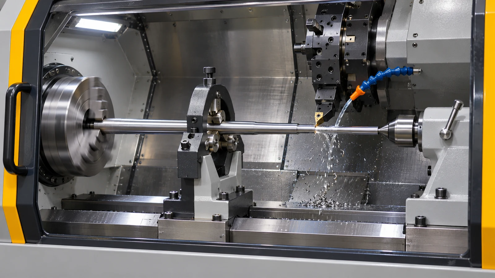
Alignment and setup: spindle-to-axis geometry, turret alignment, tool center height, jaw condition, and datum transfer can create a systematic trend. Verify with the machine maker’s method and a repeatable reference, rather than compensating a single part by eye.
Thermal change: machine warm-up, coolant condition, part temperature, and long cycle variation can shift dimensions. Compare measurements at a controlled temperature and at consistent points in the production cycle before changing offsets.
Tool and program effects: a worn edge, insert seating, nose-radius compensation, taper interpolation, or an incorrect work offset can produce a predictable dimensional change. Review the program path and tool data against the drawing, then confirm the reference point on a safe test part.
JUCHENG’s CNC 선삭 공정 context is relevant when the part is rotational; broader CNC 가공 공정 계획 helps when the taper appears after a datum transfer or a later finishing operation. These pages describe process context, not a guaranteed correction for a specific machine.
Correct the route without masking the cause
Once a test isolates the source, make one correction, repeat the same cut, and compare the same measurement map. A tool offset can compensate a stable, understood size bias. It cannot safely correct a changing taper caused by deflection, thermal drift, or inconsistent clamping. Record the adjustment and the condition under which it is valid.
If the part changes after unclamping, review the clamping sequence and material removal balance. If the error grows with unsupported length, review the support and cutting-force path. If it follows a particular tool or station, inspect tool seating, offset, and turret condition. Avoid increasing tailstock pressure or adding a broad offset before establishing which mechanism is active; either can make one measurement look better while shifting another feature.
Tie the drawing requirement to inspection
Before production, agree on the datum, measurement locations, instrument, and acceptance condition for the cylindrical feature. Size at two ends alone does not establish roundness, cylindricity, or coaxiality. If the function depends on those characteristics, the drawing should identify the relevant control and datum scheme, and the inspection plan should use a method that evaluates it.
For a supplier review, share the drawing revision, material and stock condition, quantity, critical diameters and lengths, support or assembly interfaces, and any required inspection report. The correct correction depends on that combination; a universal taper limit or offset rule cannot replace the drawing.
자주 묻는 질문
Does taper on a CNC-turned part always mean the tailstock is misaligned?
No. Tailstock alignment matters when the operation uses tailstock support. A taper can also come from workpiece deflection, machine geometry, tool setup, thermal change, clamping, or the programmed path.
How many points should be measured along a turned diameter?
Use enough axial stations and angular positions to show whether the error is gradual, localized, or rotation-dependent. The exact inspection plan should match the drawing tolerance, feature length, risk, and measurement method.
Can a tool offset remove a taper?
It can correct a repeatable dimensional bias when the cause is understood and stable. It should not be used to hide changing deflection, thermal drift, or a form error that the drawing controls separately.