
홀은 단순히 직경만으로 정의되는 경우가 거의 없습니다. CNC 홀 가공 위치, 깊이, 직진도, 표면 조도, 끼워맞춤, 나사산, 카운터싱크, 칩 배출, 그리고 여러 홀 간의 관계를 제어해야 할 수 있습니다. 드릴링은 구멍을 만들지만, 그 구멍이 조립체에서 기능을 하려면 보링, 리밍, 보간, 그리고 마무리 작업이 필요할 수 있습니다. 이 가이드는 그 결정을 정리하고, 이를 더 넓은 CNC 가공 공정 개요.
홀이 수행해야 할 기능부터 시작하십시오
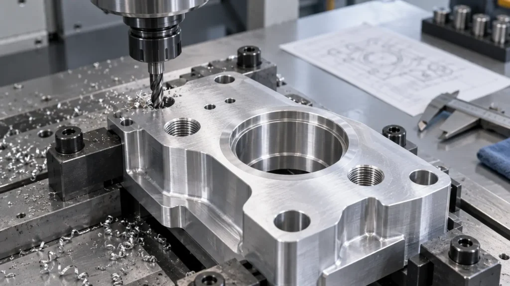
- 체결구 클리어런스: 직경, 위치, 가장자리 거리 및 버를 관리합니다.
- 위치 결정 끼워맞춤: 크기, 위치, 직각도, 원통도 및 데이텀 관계를 관리합니다.
- 베어링 또는 시일 시트: 보어 크기, 원형도, 동축도 및 표면 조도를 관리합니다.
- 유체 통로: 칩 배출, 교차부, 디버링, 청결도 및 테스트를 계획합니다.
기능이 명확해지면 공급업체는 드릴링으로 충분한지, 아니면 보링, 리밍, 보간 또는 2차 검사 단계가 필요한지 결정할 수 있습니다.
드릴링, 보링, 리밍, 보간
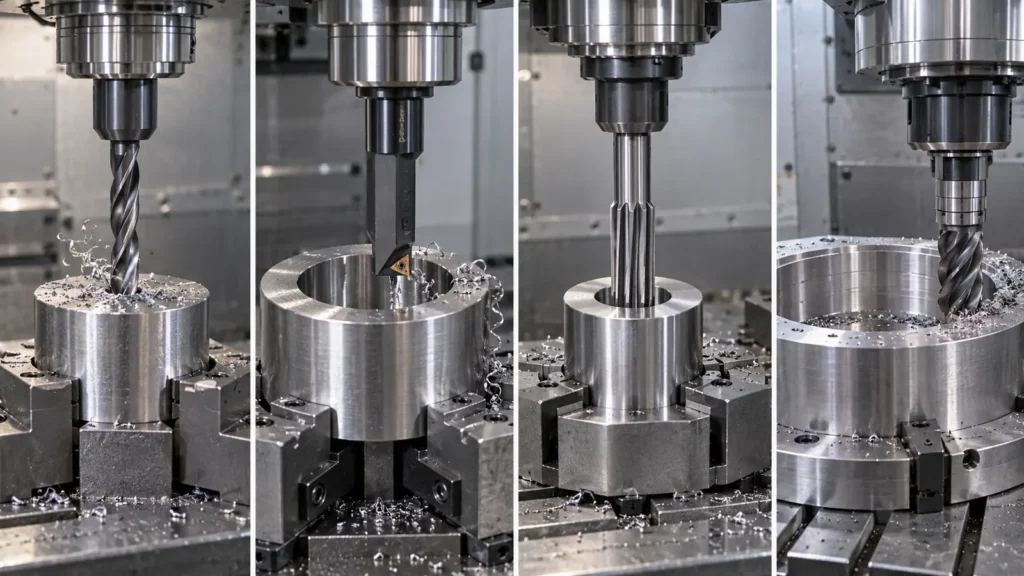
이러한 방법들은 조합할 수 있습니다. 일반적인 경로는 센터링, 거의 깊이까지 드릴링, 그런 다음 조립품이 제어된 최종 상태를 요구할 때 리밍 또는 보링을 하는 것입니다.
가공 순서 구성
- 위치와 방향을 제어하는 데이텀을 설정합니다.
- 센터링 또는 모따기로 진입부를 준비합니다.
- 드릴 길이, 냉각수, 펙 전략 및 깊이 여유를 선택합니다.
- 보링, 리밍, 보간, 카운터싱킹 또는 카운터보링으로 정밀화합니다.
- 밀봉 면, 나사산 및 교차부에서 버와 칩을 제거합니다.
- Inspect diameter, depth, position, orientation, and datum relationship.
Sequence matters near thin walls and intersecting passages. Preserve stiffness and access until the critical hole is complete.
블라인드 홀과 단차 형상
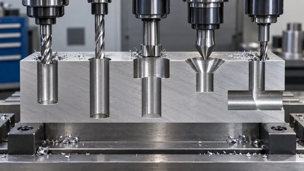
| 특징 | 위험 | Define on drawing |
|---|---|---|
| Through hole | Exit burr and breakthrough damage | Exit edge, deburring, position, diameter |
| Blind hole | Chip packing and uncertain usable depth | Total depth, usable depth, bottom form, cleanliness |
| Counterbore or countersink | Seat depth and coaxiality | Standard, diameter, angle or depth |
칩, 열, 처짐 제어
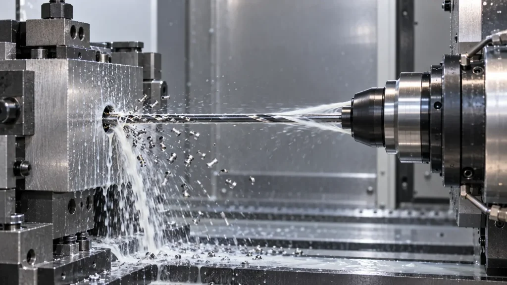
- Use pecking or chip breaking when depth and material require it.
- Deliver coolant or air where it can evacuate chips.
- Keep tool reach and runout under control.
- Use rigid workholding and preserve support around the hole.
- Plan cleaning for blind, intersecting, or fluid-channel features.
There is no universal maximum drilling depth: the practical limit depends on diameter, ratio, tool, material, machine, coolant, tolerance, and hole condition.
공차와 검사
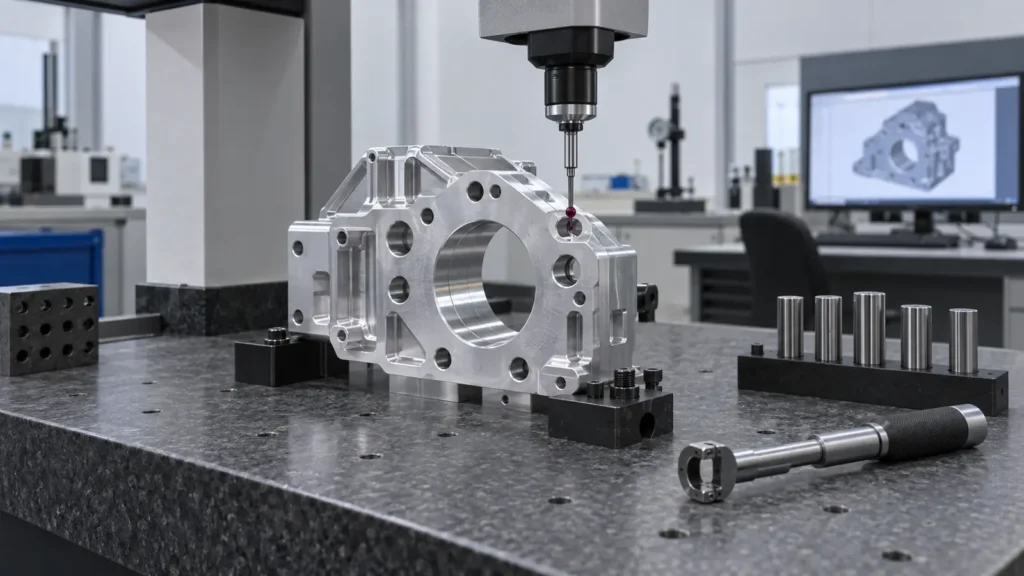
| 특성 | 중요한 이유 | Possible inspection |
|---|---|---|
| Diameter and fit | Clearance, interference, sealing, or locating | Pin gauge, bore gauge, micrometer, or CMM |
| Position | Assembly alignment and bolt-pattern function | Datum-based CMM or coordinate inspection |
| Depth and bottom | Thread engagement or fastener clearance | Depth gauge, probe, or CMM |
Measure the hole from the part datum and its mating feature, not only from an arbitrary edge. The CNC quality information can support discussion of reports and measurement requirements.
더 나은 홀을 위한 설계 선택
- Use standard drill, reamer, and thread sizes where function allows.
- Provide a stable entry face and enough edge distance.
- Define blind-hole usable depth separately from total depth.
- Avoid tight holes next to unsupported thin walls unless required.
- State whether a hole is clearance, locating, bearing, sealing, fluid, or threaded.
- Specify deburring and cleanliness for internal features.
These choices make the requirement easier to manufacture, inspect, and communicate without weakening the design intent.
RFQ 정보
- Current 3D model and 2D drawing with callouts, datums, and revision.
- Hole type, diameter, depth, fit, position, orientation, thread, and surface requirements.
- Material grade, condition, thickness, quantity, and prototype or production status.
- Deburring, cleaning, pressure, leak, coating, and assembly requirements.
- Inspection report, first article, sampling, traceability, and packaging expectations.
CNC 홀 가공 FAQ
What is the difference between drilling, boring, and reaming?
Drilling creates the initial hole, boring enlarges or corrects it, and reaming removes a controlled final allowance to improve size and surface condition.
When does a drilled hole need reaming?
Consider reaming when the final size and finish must be more controlled than the drilling route can reliably provide.
How are deep holes kept accurate?
Accuracy depends on depth ratio, tool rigidity, guidance, coolant, chip evacuation, machine condition, material, and inspection.
Why can a hole be the right size but still fail?
It may be misplaced, tilted, tapered, rough, too shallow, or not aligned with the datum or mating feature.
What should be specified for a blind hole?
Specify diameter, usable and total depth, bottom condition, thread or fit, position, chamfer, burr limits, cleanliness, and mating clearance.
Effective CNC hole machining starts with the part’s function and ends with evidence that the hole will assemble, seal, locate, carry a fastener, or carry a fluid as intended. Separating drilling, refining, deburring, cleaning, and inspection decisions prevents a simple diameter callout from hiding a difficult manufacturing requirement.