
Ein Loch ist selten nur ein Durchmesser. CNC-Lochbearbeitung möglicherweise müssen Position, Tiefe, Geradheit, Oberflächengüte, Passung, Gewinde, Senkungen, Späneabfuhr und die Beziehung zwischen mehreren Löchern kontrolliert werden. Bohren erzeugt eine Öffnung, aber Bohren (Ausbohren), Reiben, Interpolation und Schlichtoperationen können erforderlich sein, damit diese Öffnung in einer Baugruppe funktioniert. Dieser Leitfaden strukturiert die Entscheidung und verbindet sie mit dem breiteren Übersicht über den CNC-Bearbeitungsprozess.
Beginnen Sie damit, was das Loch leisten muss
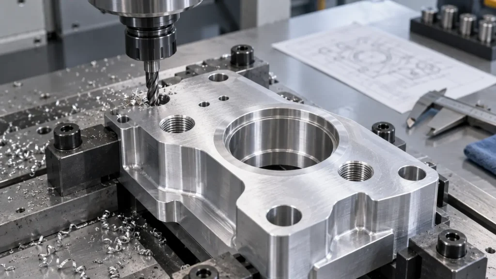
- Durchgang für Verbindungselemente: Durchmesser, Position, Randabstand und Grate kontrollieren.
- Passsitz: Größe, Position, Rechtwinkligkeit, Zylindrizität und Bezugsverhältnis kontrollieren.
- Lager- oder Dichtungssitz: Bohrungsgröße, Rundheit, Koaxialität und Oberflächengüte kontrollieren.
- Fluiddurchgang: Spanabfuhr, Schnittpunkte, Entgraten, Sauberkeit und Prüfung planen.
Sobald die Funktion klar ist, kann der Lieferant entscheiden, ob Bohren ausreicht oder ob Ausbohren, Reiben, Interpolation oder ein zweiter Prüfschritt erforderlich ist.
Bohren, Ausbohren, Reiben und Interpolation
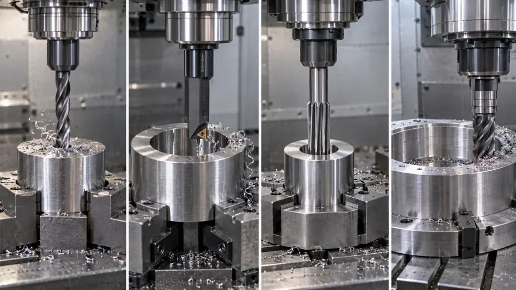
Diese Methoden können kombiniert werden. Ein typischer Ablauf kann Ankörnen, Bohren nahe der Tiefe und anschließend Reiben oder Ausspindeln umfassen, wenn die Baugruppe einen kontrollierten Endzustand erfordert.
Die Bearbeitungssequenz aufbauen
- Legen Sie das Bezugssystem fest, das Position und Orientierung steuert.
- Bereiten Sie den Eintritt mit Ankörnen oder einer Fase vor.
- Wählen Sie Bohrerlänge, Kühlmittel, Spanbruchstrategie und Tiefenzugabe.
- Verfeinern Sie mit Ausspindeln, Reiben, Interpolation, Senken oder Aufbohren.
- Entfernen Sie Grate und Späne von Dichtflächen, Gewinden und Schnittpunkten.
- Prüfen Sie Durchmesser, Tiefe, Position, Orientierung und Bezugsbeziehung.
Die Reihenfolge ist wichtig in der Nähe dünner Wände und sich kreuzender Kanäle. Erhalten Sie Steifigkeit und Zugänglichkeit, bis das kritische Loch fertig ist.
Sacklöcher und gestufte Merkmale
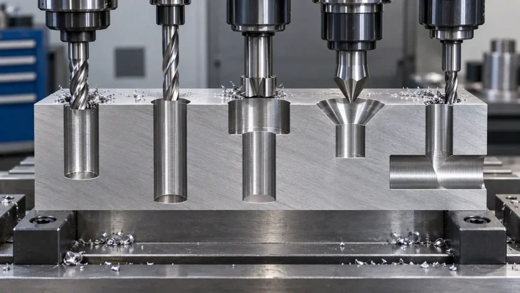
| Merkmal | Risk | Define on drawing |
|---|---|---|
| Through hole | Exit burr and breakthrough damage | Exit edge, deburring, position, diameter |
| Blind hole | Chip packing and uncertain usable depth | Total depth, usable depth, bottom form, cleanliness |
| Counterbore or countersink | Seat depth and coaxiality | Standard, diameter, angle or depth |
Späne, Wärme und Durchbiegung kontrollieren
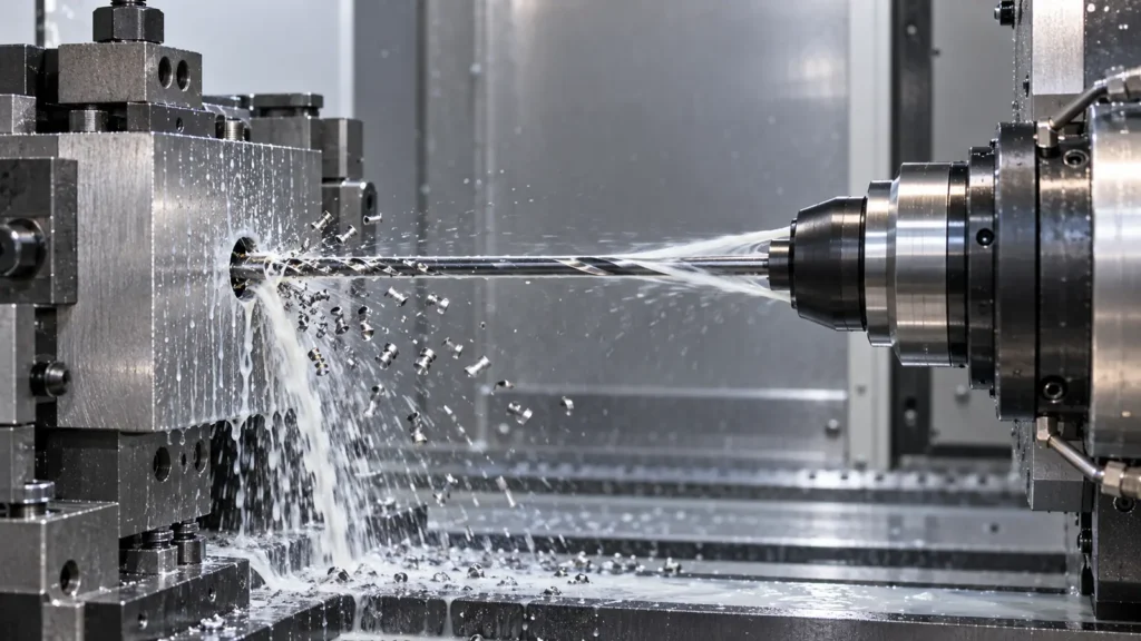
- Use pecking or chip breaking when depth and material require it.
- Deliver coolant or air where it can evacuate chips.
- Keep tool reach and runout under control.
- Use rigid workholding and preserve support around the hole.
- Plan cleaning for blind, intersecting, or fluid-channel features.
There is no universal maximum drilling depth: the practical limit depends on diameter, ratio, tool, material, machine, coolant, tolerance, and hole condition.
Toleranz und Prüfung
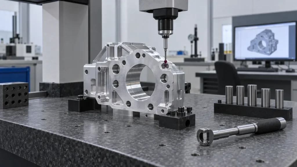
| Merkmal | Warum es wichtig ist | Possible inspection |
|---|---|---|
| Diameter and fit | Clearance, interference, sealing, or locating | Pin gauge, bore gauge, micrometer, or CMM |
| Position | Assembly alignment and bolt-pattern function | Datum-based CMM or coordinate inspection |
| Depth and bottom | Thread engagement or fastener clearance | Depth gauge, probe, or CMM |
Measure the hole from the part datum and its mating feature, not only from an arbitrary edge. The CNC quality information can support discussion of reports and measurement requirements.
Konstruktionsentscheidungen für bessere Löcher
- Use standard drill, reamer, and thread sizes where function allows.
- Provide a stable entry face and enough edge distance.
- Define blind-hole usable depth separately from total depth.
- Avoid tight holes next to unsupported thin walls unless required.
- State whether a hole is clearance, locating, bearing, sealing, fluid, or threaded.
- Specify deburring and cleanliness for internal features.
These choices make the requirement easier to manufacture, inspect, and communicate without weakening the design intent.
RFQ-Informationen
- Current 3D model and 2D drawing with callouts, datums, and revision.
- Hole type, diameter, depth, fit, position, orientation, thread, and surface requirements.
- Material grade, condition, thickness, quantity, and prototype or production status.
- Deburring, cleaning, pressure, leak, coating, and assembly requirements.
- Inspection report, first article, sampling, traceability, and packaging expectations.
FAQs zur CNC-Lochbearbeitung
What is the difference between drilling, boring, and reaming?
Drilling creates the initial hole, boring enlarges or corrects it, and reaming removes a controlled final allowance to improve size and surface condition.
When does a drilled hole need reaming?
Consider reaming when the final size and finish must be more controlled than the drilling route can reliably provide.
How are deep holes kept accurate?
Accuracy depends on depth ratio, tool rigidity, guidance, coolant, chip evacuation, machine condition, material, and inspection.
Why can a hole be the right size but still fail?
It may be misplaced, tilted, tapered, rough, too shallow, or not aligned with the datum or mating feature.
What should be specified for a blind hole?
Specify diameter, usable and total depth, bottom condition, thread or fit, position, chamfer, burr limits, cleanliness, and mating clearance.
Effective CNC hole machining starts with the part’s function and ends with evidence that the hole will assemble, seal, locate, carry a fastener, or carry a fluid as intended. Separating drilling, refining, deburring, cleaning, and inspection decisions prevents a simple diameter callout from hiding a difficult manufacturing requirement.