
CNC 밀링 공정 계획은 기계 카탈로그가 아니라 부품의 기능적 특징에서 시작해야 합니다. 포켓, 홀, 리브, 경사면, 얇은 벽, 데이텀, 외관 표면은 각각 커터 접근, 공작물 고정, 축 운동, 검사에 서로 다른 요구를 제기합니다. 이 가이드는 엔지니어와 구매자가 도면을 실용적인 밀링 공정으로 전환하는 방법, 3축, 4축 또는 5축 가공이 언제 적합한지, 그리고 어떤 결정이 끼워맞춤과 반복성을 보호하는지 설명합니다. 더 넓은 제조 순서는 다음을 참조하십시오. CNC 가공 공정 개요.
부품의 기능적 특징에서 시작하라
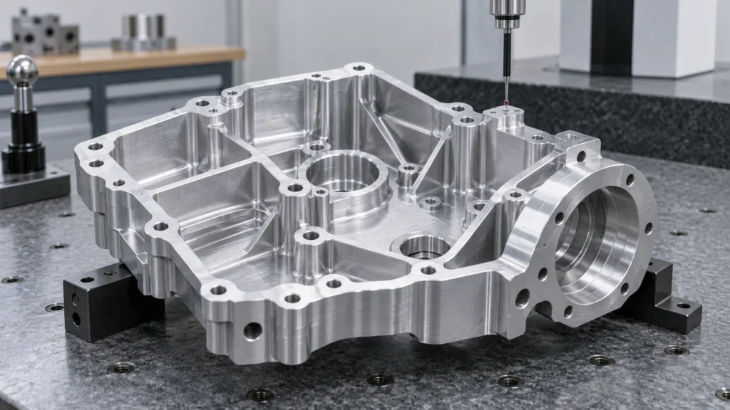
유용한 밀링 계획은 부품을 기능적 특징 그룹으로 분리하는 것에서 시작합니다:
- 데이텀 및 위치 결정 면: 부품의 검사 및 조립 기준을 설정하는 표면.
- 재료 제거 형상: 포켓, 슬롯, 단차, 리브, 보스 및 외부 프로파일.
- 연결 형상: 볼트 구멍, 다월 구멍, 탭 구멍, 카운터보어 및 장착 패턴.
- 기능성 표면: 밀봉 면, 베어링 시트, 슬라이딩 면, 열 인터페이스 및 정렬 패드.
- 접근 민감 형상: 깊은 캐비티, 좁은 채널, 언더컷, 경사 벽 및 작은 내부 반경.
- 외관 민감 영역: 공구 자국, 버, 스크래치 또는 일관되지 않은 질감이 문제가 되는 가시 면.
형상 분류는 공정을 바꿉니다. 무게만 제거하는 포켓은 베어링을 위치시키는 포켓과 다른 전략을 허용할 수 있습니다. 다월에 사용되는 구멍은 클리어런스 구멍과 다른 검사 계획이 필요합니다. 모든 표면을 동일 우선순위의 가공 대상으로 취급하면 불필요한 비용이 발생하는 동시에 진정으로 중요한 관계가 불충분하게 정의되는 경우가 많습니다.
공구를 선택하기 전에 특징 맵을 작성하라
형상 맵은 도면 의도와 기계에서 필요한 물리적 작업을 연결합니다. 어떤 표면을 먼저 생성해야 하는지, 어떤 형상에 지지가 필요한지, 어떤 치수가 동일한 셋업에 의존하는지 보여주어야 합니다. 이 지점에서 제조 엔지니어는 숨겨진 공차 누적을 현장 문제가 되기 전에 식별할 수 있습니다.
어떤 형상이 하나의 셋업을 공유해야 합니까?
정렬을 유지해야 하는 형상은 가능한 한 동일한 데이텀 기준에서 가공해야 합니다. 예를 들어, 보어 패턴과 그 주변의 장착면은 기본 작업 좌표계를 잃지 않고 생산할 때 더 신뢰할 수 있습니다. 부품을 다른 고정구로 옮기면 위치 결정 오차, 클램핑 변동, 그리고 칩이나 버가 안착에 영향을 미칠 새로운 기회가 생길 수 있습니다.
때로는 여러 번의 셋업이 필요합니다. 높은 부품, 5면 하우징, 깊은 포켓, 벽 뒤에 숨겨진 형상은 계획된 순서가 필요할 수 있습니다. 목표는 무조건 셋업 횟수를 최소화하는 것이 아니라, 공구 접근성과 공작물 고정 안정성을 유지하면서 통제되지 않은 데이텀 전환을 최소화하는 것입니다.
형상과 공구 접근이 어디에서 충돌하는가?
내부 코너, 포켓 깊이, 벽 높이, 작은 구멍은 요청된 형상과 강성 있고 경제적인 커터 사이의 타협을 강제할 수 있습니다. 좁은 내부 코너는 더 작은 공구, 더 긴 도달 거리, 느린 절삭, 또는 대체 공정을 필요로 할 수 있습니다. 깊은 포켓은 가공할 수 있지만, 도달 거리 대 직경 비율, 칩 배출, 진동, 검사 접근성이 견적의 일부가 됩니다.
좋은 DFM 피드백은 설계 의도를 지우지 않습니다. 그것은 어떤 치수가 기능적인지, 어떤 치수가 실용적인 반경을 사용할 수 있는지, 어떤 표면이 특별한 공정을 필요로 하는지를 식별합니다. 이러한 구분은 구매자가 막연한 “더 쉽게 만들어 달라”는 요청이 아니라 엔지니어링 가치에 기반하여 변경을 승인하는 데 도움이 됩니다.”
특징 맵을 밀링 계획으로 전환하라
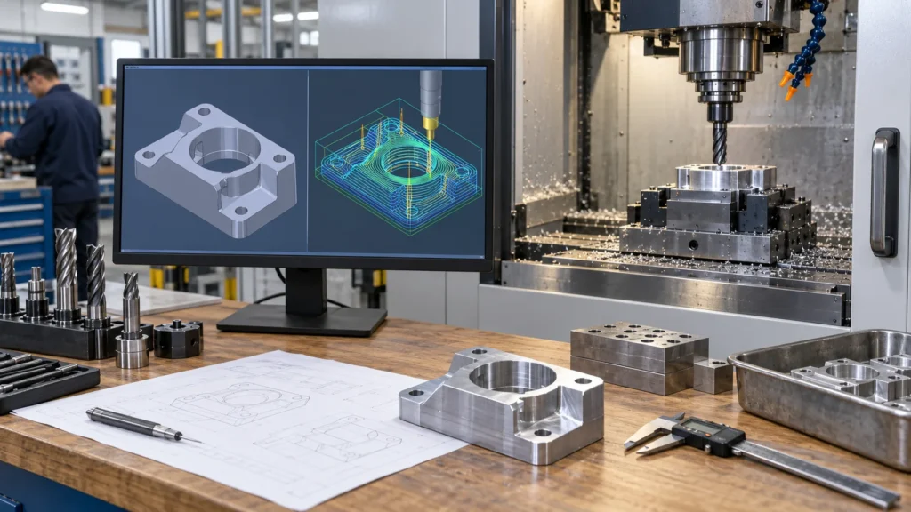
밀링 순서는 무엇을 보호해야 하는가?
순서는 안정적인 위치 결정 표면을 보호하고, 마무리를 위한 충분한 소재를 보존하며, 한 작업이 나중에 사용될 형상을 손상시키지 않도록 해야 합니다. 일반적인 경로는 면취 또는 기준 생성으로 시작하여 대량 제거를 거친 후, 세미 마무리와 최종 패스로 이동합니다. 구멍, 나사, 얇은 벽, 중요한 표면은 지지, 접근, 버 방향, 측정 필요에 따라 배치됩니다.
공구 경로 검증은 홀더 간섭, 공구 도달 거리, 충돌 위험, 잔여 소재, 급속 이동, 재료 맞물림 방향을 확인해야 합니다. 시뮬레이션은 피할 수 있는 프로그래밍 오류를 줄이지만, 고정구 강성, 공구 런아웃, 재료 상태, 냉각수 공급, 칩 배출에 대한 물리적 점검을 대체하지는 않습니다.
황삭은 마무리와 어떻게 달라야 하는가?
황삭은 안전하고 효율적인 소재 제거를 중심으로 구성됩니다. 마무리는 형상, 표면 상태, 공구 안정성을 중심으로 구성됩니다. 황삭 중 예측 가능한 여유를 남기면 마무리 공구에 일관된 맞물림을 제공합니다. 한 번에 너무 많은 소재를 제거하면 열과 변형이 증가할 수 있고, 고르지 않거나 불안정한 여유를 남기면 마지막 패스가 예측 불가능해질 수 있습니다.
밀링 계획은 내부 코너와 전환부의 잔여 소재도 고려해야 합니다. 국부적 정리를 위해 더 작은 공구가 필요할 수 있지만, 전체 부품에 걸쳐 사용하면 사이클 타임과 파손 위험이 증가할 수 있습니다. 균형 잡힌 공정은 대량 작업에 가장 큰 실용적 강성 커터를 사용하고, 실제로 필요한 형상에만 더 작은 공구를 남겨둡니다.
명성이 아니라 접근성으로 축 전략을 선택하라
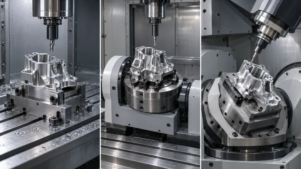
| Axis approach | Useful when | 주요 계획 질문 |
|---|---|---|
| 3-axis | Prismatic parts, open pockets, planar faces, and accessible contours | Can the part be located rigidly while the cutter reaches every critical feature? |
| 4-axis or indexed rotary | Features distributed around a part or repeated angular positions | Will rotary indexing reduce setups without weakening the locating scheme? |
| 5-axis | Compound angles, multiple faces, sculpted surfaces, and access-sensitive geometry | Will tool orientation and fewer setups improve access, accuracy, or surface control enough to justify the route? |
A 5-axis machine is not automatically the right answer. A simple plate may be faster and easier to inspect on a 3-axis center. A complex housing may benefit from fewer setups, but only if the machine, fixture, post-processor, and inspection plan are coordinated. Review the 5-axis milling capability as part of the process comparison, then make the final decision from the part’s access and tolerance requirements.
남겨진 소재에 밀링 작업을 맞춰라
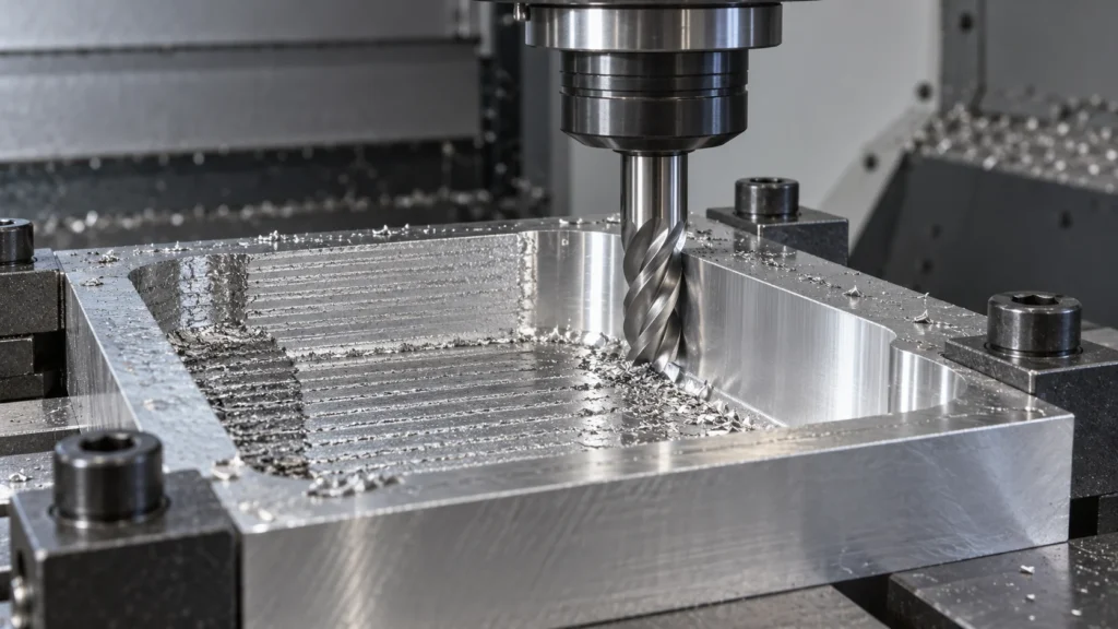
Which operation fits a common feature?
- Facing: creates a reference plane or removes stock from a broad surface.
- Pocketing: removes internal material while controlling floor, wall, corner, and chip-evacuation conditions.
- Contouring: follows an outside or inside profile where wall location and edge condition matter.
- Slotting: creates a narrow channel but may require attention to full-width engagement, deflection, and chip packing.
- Drilling and boring: establish or refine holes according to diameter, depth, position, fit, and surface needs.
- Thread milling: produces internal or external threads when the geometry and material make it useful.
- 3D finishing: controls scallop height, tool orientation, and surface continuity on curved or angled faces.
These operations are building blocks rather than a universal recipe. A deep pocket may need a roughing path, a rest-machining path, a semi-finish pass, and a final wall or floor pass. A thin rib may require the surrounding material to remain as support until late in the sequence. A finish requirement should be connected to a measurable specification, not added as an isolated promise after the toolpath is complete.
How do toolpaths affect surface and cycle time?
CNC milling toolpaths control how much material a cutter engages, how often the tool changes direction, and how the cutting load moves through the part. Roughing strategies prioritize stable removal and chip evacuation. Finishing strategies prioritize consistent engagement, step-over, tool orientation, and the direction of visible marks.
A shorter toolpath is not always the lower-risk toolpath. Aggressive engagement can reduce theoretical cycle time while increasing tool wear, chatter, heat, or rework. The useful target is a repeatable process with a predictable inspection result, not the fastest first-piece cut.
셋업 중 데이텀 무결성을 보호하라
A stable program can still produce a misplaced part when the physical setup is weak. CNC milling setup planning defines the stock orientation, work coordinate system, fixture, clamps, tool offsets, probing, and first-piece checks. The setup should restrain movement without distorting thin walls, sealing faces, or flexible plastic features.
What makes CNC milling workholding reliable?
Reliable CNC milling workholding locates the part from surfaces that reflect the drawing’s datum structure and supports the cutting forces created by the toolpath. Clamps should not obstruct critical access, create avoidable marks, or load a thin section so heavily that the part moves after release.
Multi-sided parts may need soft jaws, a fixture plate, modular locating, or a planned sequence of reorientations. Each additional setup should have a defined reason: access, support, inspection, or a required manufacturing feature. Re-clamping without a controlled locating method turns a dimensional requirement into an operator-dependent result.
When should probing be included?
Probing can help establish work coordinates, verify stock location, check selected features, and detect setup variation before a full run. It is most useful when connected to a defined control plan. Probing is not a substitute for a final inspection method, and it should not be treated as proof that every tolerance on the drawing has been measured.
소재 거동이 절삭 조건을 결정하게 하라
Material choice changes the milling route. Aluminum, stainless steel, titanium, brass, engineering plastics, and high-temperature materials differ in hardness, thermal behavior, chip formation, burr tendency, stiffness, and sensitivity to clamping. Material grade and condition should be confirmed before the process is quoted, not after a toolpath has already been selected.
| 소재 거동 | Milling concern | 계획 대응 |
|---|---|---|
| High ductility or gummy chips | Built-up edge, burrs, and chip packing | Use suitable sharp tooling, chip evacuation, coolant, and edge-control planning |
| High hardness or work hardening | Tool wear, heat, and unstable engagement | Control tool engagement, rigidity, cutting conditions, and tool life |
| Low stiffness or thermal sensitivity | Deflection, deformation, and dimensional drift | Reduce clamping distortion, shorten tool reach, and plan staged removal and inspection |
사이트의 CNC milling materials page as a starting point for material-route discussions, then confirm the exact grade, condition, finish, and certification requirements in the RFQ. Cutting speed, feed, depth of cut, radial engagement, tool diameter, and coolant are process variables; they should not be presented as universal numbers without the machine, tool, material, and geometry context.
밀링이 최선의 공정이 아닐 때를 알아라
A professional process plan includes the option not to mill a feature in the same way as the rest of the part. Rotational geometry may be more efficient on a turning center. A part with both turned and milled features may benefit from turn-mill machining when additional setups would threaten alignment. Certain conductive profiles or hardened features may call for Wire EDM, while selected precision surfaces may be finished by grinding.
Process selection should consider geometry, material, quantity, tolerance, surface requirements, setup risk, and inspection. Choosing 5-axis milling for a part that does not need its access can add programming and fixture complexity. Choosing 3-axis milling for a part that needs repeated reorientation can create datum-transfer risk. The right route is the one that delivers the required features with controlled evidence.
This boundary matters for buyers because a quotation is more useful when it explains its assumptions. Ask which features are milled, which require secondary operations, how many setups are planned, and which dimensions will be verified at each stage.
부품을 작동하게 만드는 특징을 검증하라
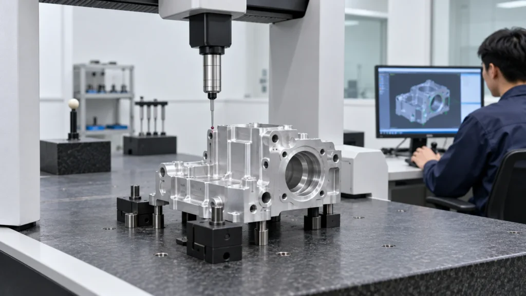
Which milling features usually need special attention?
- Datum faces and their relationship to the inspection coordinate system.
- Hole location, diameter, depth, thread condition, counterbore, and countersink.
- Pocket floor depth, wall position, internal corner radius, and remaining wall thickness.
- Flatness, perpendicularity, parallelism, profile, and the relationship between multiple setups.
- Thin walls, flexible ribs, sealing surfaces, and features that may move after unclamping.
- Surface roughness, burr condition, cleanliness, coating allowance, and cosmetic zones where specified.
Manual gauges may be suitable for straightforward dimensions. Probing, height measurement, optical inspection, or CMM measurement may be selected when geometry and tolerance relationships require more evidence. The measurement method must match the characteristic; a CMM report is not automatically meaningful if the drawing revision, datums, or evaluation method are unclear.
When supplier quality documentation matters, review the CNC quality management information and define the exact reports required for the project. Quality expectations should be tied to the drawing and application rather than expressed only as “high precision.”
가공 파트너에게 사용 가능한 RFQ 패키지를 제공하라
A milling quotation becomes more accurate when the supplier can see the design intent, not just the solid model. Provide the current 3D CAD file and controlled 2D drawing together, then identify the information that changes the process route:
- Part identity: part number, revision, quantity, forecast, and prototype or production status.
- 재질: exact grade, condition, hardness where relevant, certification, and any fluid or temperature exposure.
- Feature requirements: datums, fits, hole and thread specifications, critical profiles, thin walls, and sealing surfaces.
- Finish: surface roughness, appearance zones, masking, anodizing, plating, passivation, polishing, or other secondary work.
- 검사: first article requirements, critical dimensions, CMM or gauge reports, sampling, traceability, and acceptance criteria.
- Delivery: target window, packaging, destination, repeat-order expectations, and any release documentation.
Explain what the part must do when a feature is difficult to interpret from geometry alone. That context helps the manufacturing engineer decide whether a different cutter, workholding method, axis strategy, material condition, staged inspection, or secondary process is justified. It also makes supplier quotations easier to compare because the assumptions are visible.
CNC 밀링 공정 FAQ
What is the CNC milling process used for?
The CNC milling process is used to remove material from a fixed or securely located workpiece with rotating cutting tools. It is well suited to faces, pockets, slots, holes, ribs, bosses, angled surfaces, and three-dimensional profiles in metals and engineering plastics.
When is 5-axis milling better than 3-axis milling?
5-axis milling is worth evaluating when a part has multiple compound faces, difficult tool access, sculpted surfaces, or several features that would otherwise require repeated setups. It is not automatically better for a simple prismatic part; geometry, fixture design, tolerance relationships, programming, and inspection determine the benefit.
How many setups does a milled part need?
Setup count depends on feature access, datum structure, workholding, part stiffness, and the required inspection relationships. One setup may be ideal for accessible features, while a housing or multi-sided component may need several planned orientations or a multi-axis strategy. Fewer setups are valuable only when the part remains securely located and measurable.
Does CNC milling always produce the tightest tolerance?
No. Achievable tolerance depends on feature size, material, geometry, tool reach, machine condition, workholding, thermal behavior, inspection method, and production quantity. A tolerance should describe the function of the feature, and the process should be selected to control the complete relationship rather than one isolated dimension.
What should buyers ask before approving a milling quote?
Ask which machine and axis strategy are planned, how the part will be located, how many setups are required, which features are critical, what material condition is assumed, how surfaces will be finished, and which inspection documents will be supplied. Clear assumptions make price, lead time, and technical risk easier to compare.
Effective milling is a controlled chain from functional feature definition to tool access, workholding, material behavior, cutting strategy, and inspection. When those decisions are made together, engineers can choose the simplest process that protects the part’s real requirements and gives production a repeatable path to follow.