
Процесс фрезерования на станке с ЧПУ планирование должно начинаться с функциональных особенностей детали, а не с каталога станков. Карманы, отверстия, рёбра, наклонные поверхности, тонкие стенки, базы и декоративные поверхности предъявляют разные требования к доступу инструмента, закреплению заготовки, перемещению по осям и контролю. В этом руководстве объясняется, как инженеры и закупщики могут превратить чертёж в практический маршрут фрезерования, когда имеет смысл 3-осевая, 4-осевая или 5-осевая обработка, и какие решения обеспечивают точность посадки и повторяемость. Для более широкой последовательности производства см. Обзор процесса обработки на станках с ЧПУ.
Начните с функциональных особенностей детали
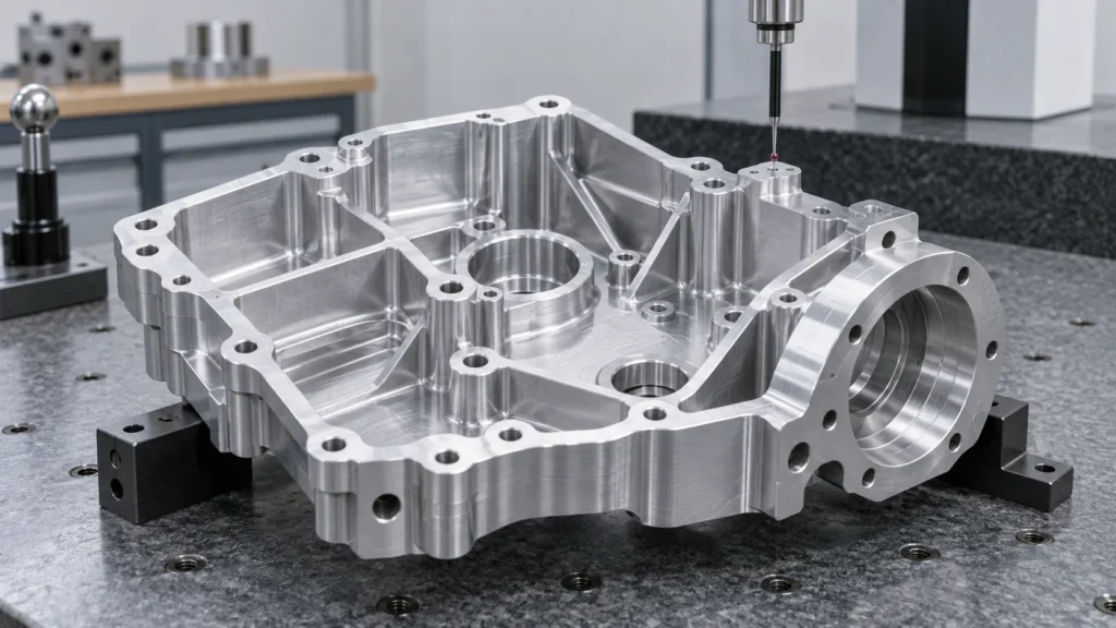
Полезный план фрезерования начинается с разделения детали на функциональные группы элементов:
- Базы и установочные поверхности: поверхности, которые задают базу для контроля и сборки детали.
- Элементы съёма материала: карманы, пазы, уступы, рёбра, бобышки и наружные контуры.
- Соединительные элементы: отверстия под болты, отверстия под штифты, резьбовые отверстия, цековки и монтажные схемы.
- Функциональные поверхности: уплотнительные поверхности, посадочные места под подшипники, поверхности скольжения, тепловые интерфейсы и установочные площадки.
- Элементы, чувствительные к доступу: глубокие полости, узкие каналы, поднутрения, наклонные стенки и малые внутренние радиусы.
- Зоны, чувствительные к внешнему виду: видимые поверхности, где важны следы инструмента, заусенцы, царапины или неоднородная текстура.
Классификация элементов меняет процесс. Карман, который только снижает массу, допускает иную стратегию, чем карман, который служит базой для подшипника. Отверстие под штифт требует иного плана контроля, чем отверстие под крепёж с зазором. Обращение с каждой поверхностью как с равноприоритетной целью обработки часто создаёт ненужные затраты, оставляя при этом действительно важные взаимосвязи недостаточно определёнными.
Составьте карту элементов перед выбором инструментов
Карта элементов связывает замысел чертежа с физическими действиями, необходимыми на станке. Она должна показывать, какие поверхности нужно создать первыми, какие элементы требуют поддержки и какие размеры зависят от одной и той же установки. Именно на этом этапе инженер-технолог может выявить скрытую размерную цепь допусков, прежде чем она станет проблемой в цехе.
Какие элементы следует обрабатывать за одну установку?
Элементы, которые должны оставаться соосными, по возможности следует обрабатывать от одной базы. Например, схема отверстий и окружающая её монтажная поверхность могут быть надёжнее изготовлены без потери основной рабочей системы координат. Перемещение детали на другое приспособление может внести погрешность базирования, вариацию зажима и новую возможность влияния стружки или заусенцев на посадку.
Иногда необходимы несколько установок. Высокие детали, пятисторонние корпуса, глубокие карманы и элементы, скрытые за стенкой, могут потребовать запланированной последовательности. Цель не в том, чтобы минимизировать число установок любой ценой; цель — минимизировать неконтролируемый перенос баз, сохраняя при этом доступ инструмента и стабильность закрепления.
Где геометрия и доступ инструмента конфликтуют?
Внутренние углы, глубина кармана, высота стенки и малые отверстия могут вынудить к компромиссу между требуемой геометрией и жёстким, экономичным инструментом. Узкий внутренний угол может потребовать меньшего инструмента, большего вылета, более медленного резания или альтернативного процесса. Глубокие карманы можно обрабатывать, но соотношение вылета к диаметру, эвакуация стружки, вибрация и доступ для контроля становятся частью расчёта стоимости.
Хорошая обратная связь по DFM не стирает конструкторский замысел. Она определяет, какие размеры являются функциональными, где можно применить практичный радиус и какие поверхности требуют специального процесса. Такое разграничение помогает заказчику утвердить изменение исходя из инженерной ценности, а не из расплывчатого запроса “сделать попроще”.”
Превратите карту элементов в план фрезерования
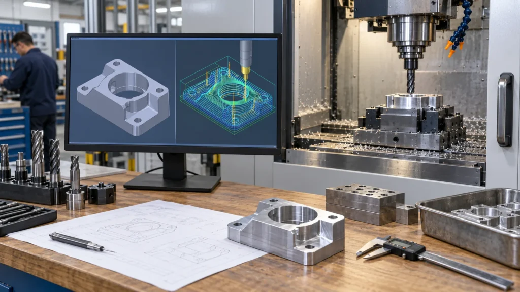
Что должна защищать последовательность фрезерования?
Последовательность должна защищать стабильные базовые поверхности, сохранять достаточный припуск для чистовой обработки и предотвращать повреждение одним переходом элемента, который будет использоваться позже. Обычный маршрут начинается с торцевания или создания баз, продолжается черновым съёмом материала, затем переходит к получистовым и чистовым проходам. Отверстия, резьбы, тонкие стенки и ответственные поверхности размещаются с учётом опоры, доступа, направления заусенцев и потребностей измерения.
Верификация траектории инструмента должна проверять зазор до держателя, вылет инструмента, риск столкновения, остаточный припуск, ускоренные перемещения и направление врезания в материал. Симуляция снижает количество предотвратимых ошибок программирования, но не заменяет физическую проверку жёсткости приспособления, биения инструмента, состояния материала, подачи СОЖ и эвакуации стружки.
Чем черновая обработка должна отличаться от чистовой?
Черновая обработка организована вокруг безопасного и эффективного съёма материала. Чистовая обработка организована вокруг геометрии, состояния поверхности и стабильности инструмента. Оставление предсказуемого припуска при черновой обработке обеспечивает чистовому инструменту постоянное врезание. Снятие слишком большого объёма материала за один раз может увеличить нагрев и отклонение; оставление неравномерного или нестабильного припуска делает последний проход непредсказуемым.
Планы фрезерования должны также учитывать остаточный материал во внутренних углах и переходах. Для локальной зачистки могут потребоваться меньшие инструменты, но их использование по всей детали может увеличить время цикла и риск поломки. Сбалансированный процесс использует наибольший практичный жёсткий инструмент для черновой работы и оставляет меньшие инструменты для элементов, которые действительно в них нуждаются.
Выбирайте стратегию по осям исходя из доступа, а не престижа
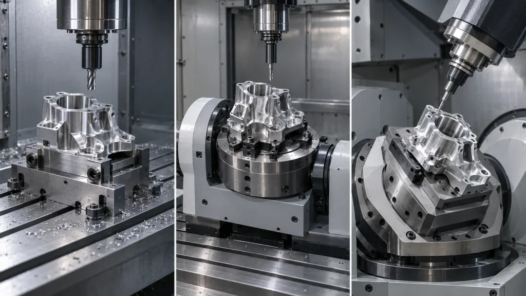
| Axis approach | Useful when | Main planning question |
|---|---|---|
| 3-осевая | Prismatic parts, open pockets, planar faces, and accessible contours | Can the part be located rigidly while the cutter reaches every critical feature? |
| 4-axis or indexed rotary | Features distributed around a part or repeated angular positions | Will rotary indexing reduce setups without weakening the locating scheme? |
| 5-осевые | Compound angles, multiple faces, sculpted surfaces, and access-sensitive geometry | Will tool orientation and fewer setups improve access, accuracy, or surface control enough to justify the route? |
A 5-axis machine is not automatically the right answer. A simple plate may be faster and easier to inspect on a 3-axis center. A complex housing may benefit from fewer setups, but only if the machine, fixture, post-processor, and inspection plan are coordinated. Review the Возможности 5-осевой фрезерной обработки as part of the process comparison, then make the final decision from the part’s access and tolerance requirements.
Согласуйте операции фрезерования с оставшимся материалом
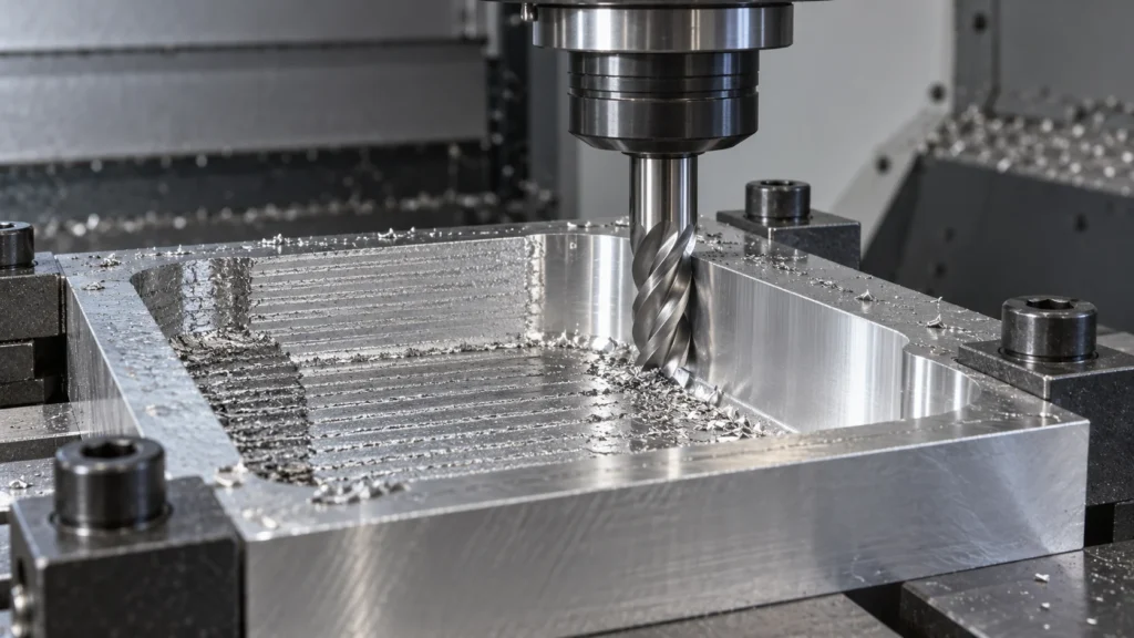
Which operation fits a common feature?
- Facing: creates a reference plane or removes stock from a broad surface.
- Pocketing: removes internal material while controlling floor, wall, corner, and chip-evacuation conditions.
- Contouring: follows an outside or inside profile where wall location and edge condition matter.
- Slotting: creates a narrow channel but may require attention to full-width engagement, deflection, and chip packing.
- Drilling and boring: establish or refine holes according to diameter, depth, position, fit, and surface needs.
- Thread milling: produces internal or external threads when the geometry and material make it useful.
- 3D finishing: controls scallop height, tool orientation, and surface continuity on curved or angled faces.
These operations are building blocks rather than a universal recipe. A deep pocket may need a roughing path, a rest-machining path, a semi-finish pass, and a final wall or floor pass. A thin rib may require the surrounding material to remain as support until late in the sequence. A finish requirement should be connected to a measurable specification, not added as an isolated promise after the toolpath is complete.
How do toolpaths affect surface and cycle time?
CNC milling toolpaths control how much material a cutter engages, how often the tool changes direction, and how the cutting load moves through the part. Roughing strategies prioritize stable removal and chip evacuation. Finishing strategies prioritize consistent engagement, step-over, tool orientation, and the direction of visible marks.
A shorter toolpath is not always the lower-risk toolpath. Aggressive engagement can reduce theoretical cycle time while increasing tool wear, chatter, heat, or rework. The useful target is a repeatable process with a predictable inspection result, not the fastest first-piece cut.
Обеспечьте целостность баз при установке
A stable program can still produce a misplaced part when the physical setup is weak. CNC milling setup planning defines the stock orientation, work coordinate system, fixture, clamps, tool offsets, probing, and first-piece checks. The setup should restrain movement without distorting thin walls, sealing faces, or flexible plastic features.
What makes CNC milling workholding reliable?
Reliable CNC milling workholding locates the part from surfaces that reflect the drawing’s datum structure and supports the cutting forces created by the toolpath. Clamps should not obstruct critical access, create avoidable marks, or load a thin section so heavily that the part moves after release.
Multi-sided parts may need soft jaws, a fixture plate, modular locating, or a planned sequence of reorientations. Each additional setup should have a defined reason: access, support, inspection, or a required manufacturing feature. Re-clamping without a controlled locating method turns a dimensional requirement into an operator-dependent result.
When should probing be included?
Probing can help establish work coordinates, verify stock location, check selected features, and detect setup variation before a full run. It is most useful when connected to a defined control plan. Probing is not a substitute for a final inspection method, and it should not be treated as proof that every tolerance on the drawing has been measured.
Пусть поведение материала определяет режимы резания
Material choice changes the milling route. Aluminum, stainless steel, titanium, brass, engineering plastics, and high-temperature materials differ in hardness, thermal behavior, chip formation, burr tendency, stiffness, and sensitivity to clamping. Material grade and condition should be confirmed before the process is quoted, not after a toolpath has already been selected.
| Поведение материала | Milling concern | Меры при планировании |
|---|---|---|
| High ductility or gummy chips | Built-up edge, burrs, and chip packing | Use suitable sharp tooling, chip evacuation, coolant, and edge-control planning |
| High hardness or work hardening | Tool wear, heat, and unstable engagement | Control tool engagement, rigidity, cutting conditions, and tool life |
| Low stiffness or thermal sensitivity | Deflection, deformation, and dimensional drift | Reduce clamping distortion, shorten tool reach, and plan staged removal and inspection |
Используйте сайт CNC milling materials page as a starting point for material-route discussions, then confirm the exact grade, condition, finish, and certification requirements in the RFQ. Cutting speed, feed, depth of cut, radial engagement, tool diameter, and coolant are process variables; they should not be presented as universal numbers without the machine, tool, material, and geometry context.
Знайте, когда фрезерование не является лучшим маршрутом
A professional process plan includes the option not to mill a feature in the same way as the rest of the part. Rotational geometry may be more efficient on a turning center. A part with both turned and milled features may benefit from turn-mill machining when additional setups would threaten alignment. Certain conductive profiles or hardened features may call for Wire EDM, while selected precision surfaces may be finished by grinding.
Process selection should consider geometry, material, quantity, tolerance, surface requirements, setup risk, and inspection. Choosing 5-axis milling for a part that does not need its access can add programming and fixture complexity. Choosing 3-axis milling for a part that needs repeated reorientation can create datum-transfer risk. The right route is the one that delivers the required features with controlled evidence.
This boundary matters for buyers because a quotation is more useful when it explains its assumptions. Ask which features are milled, which require secondary operations, how many setups are planned, and which dimensions will be verified at each stage.
Проверьте элементы, которые обеспечивают работу детали
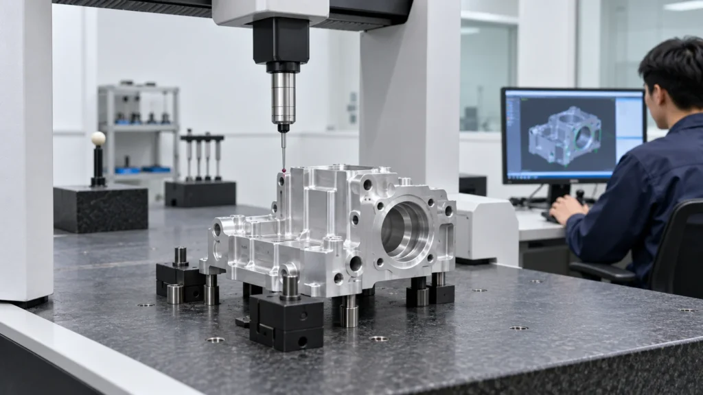
Which milling features usually need special attention?
- Datum faces and their relationship to the inspection coordinate system.
- Hole location, diameter, depth, thread condition, counterbore, and countersink.
- Pocket floor depth, wall position, internal corner radius, and remaining wall thickness.
- Flatness, perpendicularity, parallelism, profile, and the relationship between multiple setups.
- Thin walls, flexible ribs, sealing surfaces, and features that may move after unclamping.
- Surface roughness, burr condition, cleanliness, coating allowance, and cosmetic zones where specified.
Manual gauges may be suitable for straightforward dimensions. Probing, height measurement, optical inspection, or CMM measurement may be selected when geometry and tolerance relationships require more evidence. The measurement method must match the characteristic; a CMM report is not automatically meaningful if the drawing revision, datums, or evaluation method are unclear.
When supplier quality documentation matters, review the CNC quality management information and define the exact reports required for the project. Quality expectations should be tied to the drawing and application rather than expressed only as “high precision.”
Предоставьте партнёру по обработке пригодный пакет RFQ
A milling quotation becomes more accurate when the supplier can see the design intent, not just the solid model. Provide the current 3D CAD file and controlled 2D drawing together, then identify the information that changes the process route:
- Part identity: part number, revision, quantity, forecast, and prototype or production status.
- Материал: exact grade, condition, hardness where relevant, certification, and any fluid or temperature exposure.
- Feature requirements: datums, fits, hole and thread specifications, critical profiles, thin walls, and sealing surfaces.
- Finish: surface roughness, appearance zones, masking, anodizing, plating, passivation, polishing, or other secondary work.
- Контроль: first article requirements, critical dimensions, CMM or gauge reports, sampling, traceability, and acceptance criteria.
- Delivery: target window, packaging, destination, repeat-order expectations, and any release documentation.
Explain what the part must do when a feature is difficult to interpret from geometry alone. That context helps the manufacturing engineer decide whether a different cutter, workholding method, axis strategy, material condition, staged inspection, or secondary process is justified. It also makes supplier quotations easier to compare because the assumptions are visible.
Часто задаваемые вопросы о процессе фрезерования на станках с ЧПУ
What is the CNC milling process used for?
The CNC milling process is used to remove material from a fixed or securely located workpiece with rotating cutting tools. It is well suited to faces, pockets, slots, holes, ribs, bosses, angled surfaces, and three-dimensional profiles in metals and engineering plastics.
When is 5-axis milling better than 3-axis milling?
5-axis milling is worth evaluating when a part has multiple compound faces, difficult tool access, sculpted surfaces, or several features that would otherwise require repeated setups. It is not automatically better for a simple prismatic part; geometry, fixture design, tolerance relationships, programming, and inspection determine the benefit.
How many setups does a milled part need?
Setup count depends on feature access, datum structure, workholding, part stiffness, and the required inspection relationships. One setup may be ideal for accessible features, while a housing or multi-sided component may need several planned orientations or a multi-axis strategy. Fewer setups are valuable only when the part remains securely located and measurable.
Does CNC milling always produce the tightest tolerance?
No. Achievable tolerance depends on feature size, material, geometry, tool reach, machine condition, workholding, thermal behavior, inspection method, and production quantity. A tolerance should describe the function of the feature, and the process should be selected to control the complete relationship rather than one isolated dimension.
What should buyers ask before approving a milling quote?
Ask which machine and axis strategy are planned, how the part will be located, how many setups are required, which features are critical, what material condition is assumed, how surfaces will be finished, and which inspection documents will be supplied. Clear assumptions make price, lead time, and technical risk easier to compare.
Effective milling is a controlled chain from functional feature definition to tool access, workholding, material behavior, cutting strategy, and inspection. When those decisions are made together, engineers can choose the simplest process that protects the part’s real requirements and gives production a repeatable path to follow.