
Proceso de fresado CNC la planificación debe comenzar con las características funcionales de la pieza, no con un catálogo de máquinas. Los bolsillos, agujeros, nervios, caras anguladas, paredes delgadas, datums y superficies cosméticas imponen cada uno demandas diferentes sobre el acceso del cortador, la sujeción de la pieza, el movimiento de los ejes y la inspección. Esta guía explica cómo los ingenieros y compradores pueden convertir un plano en una ruta de fresado práctica, cuándo tiene sentido el mecanizado de 3 ejes, 4 ejes o 5 ejes, y qué decisiones protegen el ajuste y la repetibilidad. Para conocer la secuencia de fabricación más amplia, consulte la descripción general del proceso de mecanizado CNC.
Comience por las características funcionales de la pieza
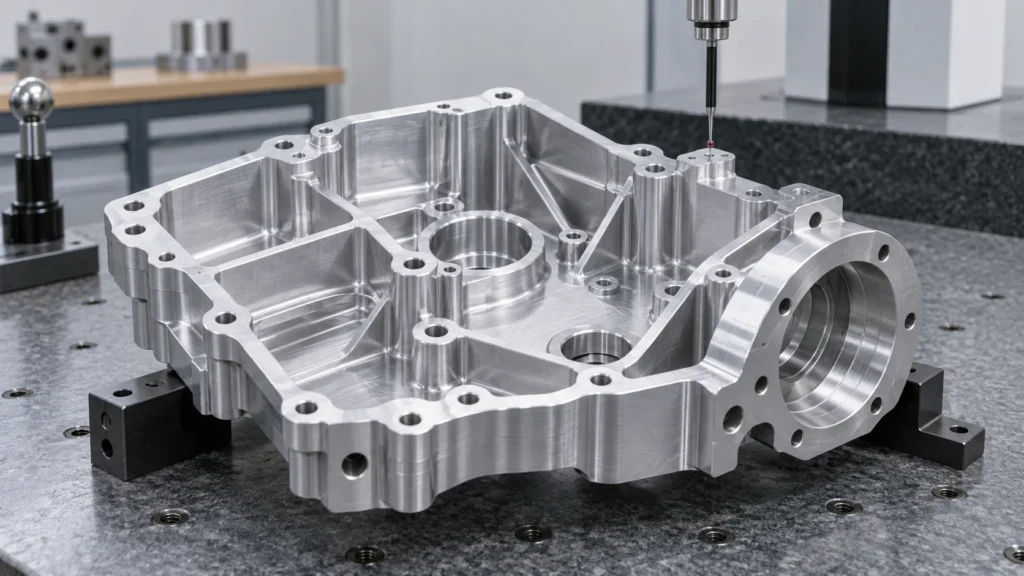
Un plan de mecanizado útil comienza separando la pieza en grupos de características funcionales:
- Referencias y caras de localización: superficies que establecen la referencia de inspección y ensamblaje de la pieza.
- Características de eliminación de material: cavidades, ranuras, escalones, nervios, resaltes y perfiles externos.
- Características de conexión: agujeros para pernos, agujeros para pasadores, agujeros roscados, avellanados y patrones de montaje.
- Superficies funcionales: caras de sellado, asientos de rodamientos, superficies de deslizamiento, interfaces térmicas y almohadillas de alineación.
- Características sensibles al acceso: cavidades profundas, canales estrechos, socavados, paredes inclinadas y radios internos pequeños.
- Zonas sensibles a la apariencia: caras visibles donde las marcas de herramienta, rebabas, rayones o una textura inconsistente importan.
La clasificación de características cambia el proceso. Una cavidad que solo elimina peso puede tolerar una estrategia diferente de una cavidad que aloja un rodamiento. Un agujero utilizado para un pasador requiere un plan de inspección diferente de un agujero de holgura. Tratar cada superficie como un objetivo de mecanizado de igual prioridad a menudo crea costos innecesarios mientras deja las relaciones verdaderamente importantes poco definidas.
Elabore un mapa de características antes de elegir las herramientas
Un mapa de características conecta la intención del plano con las acciones físicas requeridas en la máquina. Debe mostrar qué superficies deben crearse primero, qué características necesitan soporte y qué dimensiones dependen de la misma configuración. Este es el punto donde un ingeniero de fabricación puede identificar una acumulación de tolerancias oculta antes de que se convierta en un problema en el taller.
¿Qué características deben compartir una misma configuración?
Las características que deben permanecer alineadas deben mecanizarse desde el mismo datum de referencia siempre que sea práctico. Por ejemplo, un patrón de barrenos y su cara de montaje circundante pueden ser más fiables cuando se producen sin perder el sistema de coordenadas de trabajo primario. Mover la pieza a otro dispositivo de sujeción puede introducir error de localización, variación de sujeción y una nueva oportunidad para que las virutas o rebabas afecten el asentamiento.
A veces son necesarias múltiples configuraciones. Las piezas altas, las carcasas de cinco caras, las cavidades profundas y las características ocultas detrás de una pared pueden requerir una secuencia planificada. El objetivo no es minimizar el número de configuraciones a cualquier costo; el objetivo es minimizar la transferencia de datum no controlada mientras se mantiene el acceso a la herramienta y la estabilidad de la sujeción.
¿Dónde entran en conflicto la geometría y el acceso a la herramienta?
Las esquinas internas, la profundidad de la cavidad, la altura de la pared y los barrenos pequeños pueden forzar un compromiso entre la geometría solicitada y una herramienta de corte rígida y económica. Una esquina interna estrecha puede requerir una herramienta más pequeña, un alcance mayor, corte más lento o un proceso alternativo. Las cavidades profundas se pueden mecanizar, pero la relación alcance-diámetro, la evacuación de virutas, la vibración y el acceso para inspección pasan a formar parte de la cotización.
La buena retroalimentación de DFM no borra la intención del diseño. Identifica qué dimensiones son funcionales, cuáles pueden usar un radio práctico y qué superficies necesitan un proceso especial. Esa distinción ayuda al comprador a aprobar un cambio basado en el valor de ingeniería en lugar de en una solicitud vaga de “hacerlo más fácil”.”
Convierta el mapa de características en un plan de fresado
¿Qué debe proteger la secuencia de mecanizado?
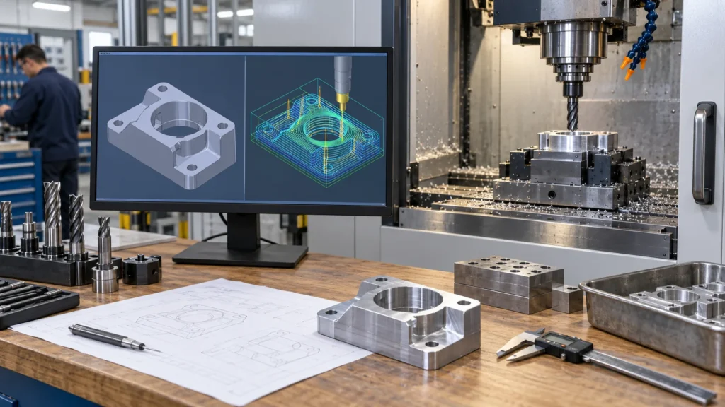
La secuencia debe proteger las superficies de localización estables, preservar suficiente material para el acabado y evitar que una operación dañe una característica que se utilizará más adelante. Una ruta común comienza con el careado o la creación de referencias, continúa con el desbaste de material y luego pasa al semiacabado y a las pasadas finales. Los barrenos, las roscas, las paredes delgadas y las superficies críticas se colocan según el soporte, el acceso, la dirección de las rebabas y las necesidades de medición.
La verificación de la trayectoria de la herramienta debe comprobar la holgura del portaherramientas, el alcance de la herramienta, el riesgo de colisión, el material restante, los movimientos rápidos y la dirección del contacto con el material. La simulación reduce los errores de programación evitables, pero no sustituye una comprobación física de la rigidez del dispositivo de sujeción, la excentricidad de la herramienta, el estado del material, el suministro de refrigerante y la evacuación de virutas.
¿En qué debe diferir el desbaste del acabado?
El desbaste se organiza en torno a la eliminación de material segura y eficiente. El acabado se organiza en torno a la geometría, el estado de la superficie y la estabilidad de la herramienta. Dejar un sobreespesor predecible durante el desbaste proporciona a la herramienta de acabado un contacto constante. Eliminar demasiado material de una vez puede aumentar el calor y la deflexión; dejar un sobreespesor desigual o inestable puede hacer que la última pasada sea impredecible.
Los planes de mecanizado también deben tener en cuenta el material restante en esquinas internas y transiciones. Pueden necesitarse herramientas más pequeñas para la limpieza local, pero usarlas en toda la pieza puede aumentar el tiempo de ciclo y el riesgo de rotura. Un proceso equilibrado utiliza la herramienta de corte rígida más grande que sea práctica para el trabajo en bruto y reserva las herramientas más pequeñas para las características que realmente las necesitan.
Elija la estrategia de ejes por el acceso, no por el prestigio
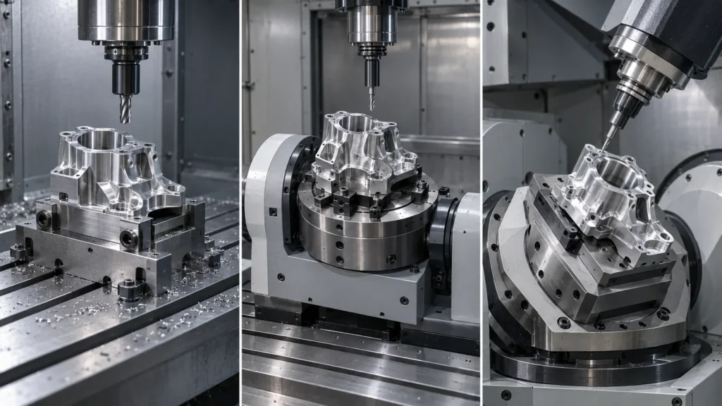
| Axis approach | Useful when | Main planning question |
|---|---|---|
| 3 ejes | Prismatic parts, open pockets, planar faces, and accessible contours | Can the part be located rigidly while the cutter reaches every critical feature? |
| 4-axis or indexed rotary | Features distributed around a part or repeated angular positions | Will rotary indexing reduce setups without weakening the locating scheme? |
| 5-axis | Compound angles, multiple faces, sculpted surfaces, and access-sensitive geometry | Will tool orientation and fewer setups improve access, accuracy, or surface control enough to justify the route? |
A 5-axis machine is not automatically the right answer. A simple plate may be faster and easier to inspect on a 3-axis center. A complex housing may benefit from fewer setups, but only if the machine, fixture, post-processor, and inspection plan are coordinated. Review the 5-axis milling capability as part of the process comparison, then make the final decision from the part’s access and tolerance requirements.
Adapte las operaciones de fresado al material restante
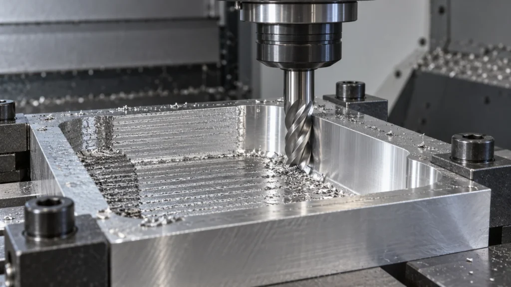
Which operation fits a common feature?
- Refrentado: creates a reference plane or removes stock from a broad surface.
- Pocketing: removes internal material while controlling floor, wall, corner, and chip-evacuation conditions.
- Contouring: follows an outside or inside profile where wall location and edge condition matter.
- Slotting: creates a narrow channel but may require attention to full-width engagement, deflection, and chip packing.
- Drilling and boring: establish or refine holes according to diameter, depth, position, fit, and surface needs.
- Thread milling: produces internal or external threads when the geometry and material make it useful.
- 3D finishing: controls scallop height, tool orientation, and surface continuity on curved or angled faces.
These operations are building blocks rather than a universal recipe. A deep pocket may need a roughing path, a rest-machining path, a semi-finish pass, and a final wall or floor pass. A thin rib may require the surrounding material to remain as support until late in the sequence. A finish requirement should be connected to a measurable specification, not added as an isolated promise after the toolpath is complete.
How do toolpaths affect surface and cycle time?
CNC milling toolpaths control how much material a cutter engages, how often the tool changes direction, and how the cutting load moves through the part. Roughing strategies prioritize stable removal and chip evacuation. Finishing strategies prioritize consistent engagement, step-over, tool orientation, and the direction of visible marks.
A shorter toolpath is not always the lower-risk toolpath. Aggressive engagement can reduce theoretical cycle time while increasing tool wear, chatter, heat, or rework. The useful target is a repeatable process with a predictable inspection result, not the fastest first-piece cut.
Proteja la integridad de los datums durante la preparación
A stable program can still produce a misplaced part when the physical setup is weak. CNC milling setup planning defines the stock orientation, work coordinate system, fixture, clamps, tool offsets, probing, and first-piece checks. The setup should restrain movement without distorting thin walls, sealing faces, or flexible plastic features.
What makes CNC milling workholding reliable?
Reliable CNC milling workholding locates the part from surfaces that reflect the drawing’s datum structure and supports the cutting forces created by the toolpath. Clamps should not obstruct critical access, create avoidable marks, or load a thin section so heavily that the part moves after release.
Multi-sided parts may need soft jaws, a fixture plate, modular locating, or a planned sequence of reorientations. Each additional setup should have a defined reason: access, support, inspection, or a required manufacturing feature. Re-clamping without a controlled locating method turns a dimensional requirement into an operator-dependent result.
When should probing be included?
Probing can help establish work coordinates, verify stock location, check selected features, and detect setup variation before a full run. It is most useful when connected to a defined control plan. Probing is not a substitute for a final inspection method, and it should not be treated as proof that every tolerance on the drawing has been measured.
Deje que el comportamiento del material determine las condiciones de corte
Material choice changes the milling route. Aluminum, stainless steel, titanium, brass, engineering plastics, and high-temperature materials differ in hardness, thermal behavior, chip formation, burr tendency, stiffness, and sensitivity to clamping. Material grade and condition should be confirmed before the process is quoted, not after a toolpath has already been selected.
| Comportamiento del material | Milling concern | Respuesta de planificación |
|---|---|---|
| High ductility or gummy chips | Built-up edge, burrs, and chip packing | Use suitable sharp tooling, chip evacuation, coolant, and edge-control planning |
| High hardness or work hardening | Tool wear, heat, and unstable engagement | Control tool engagement, rigidity, cutting conditions, and tool life |
| Low stiffness or thermal sensitivity | Deflection, deformation, and dimensional drift | Reduce clamping distortion, shorten tool reach, and plan staged removal and inspection |
Utilice las CNC milling materials page as a starting point for material-route discussions, then confirm the exact grade, condition, finish, and certification requirements in the RFQ. Cutting speed, feed, depth of cut, radial engagement, tool diameter, and coolant are process variables; they should not be presented as universal numbers without the machine, tool, material, and geometry context.
Sepa cuándo el fresado no es la mejor ruta
A professional process plan includes the option not to mill a feature in the same way as the rest of the part. Rotational geometry may be more efficient on a turning center. A part with both turned and milled features may benefit from turn-mill machining when additional setups would threaten alignment. Certain conductive profiles or hardened features may call for Wire EDM, while selected precision surfaces may be finished by grinding.
Process selection should consider geometry, material, quantity, tolerance, surface requirements, setup risk, and inspection. Choosing 5-axis milling for a part that does not need its access can add programming and fixture complexity. Choosing 3-axis milling for a part that needs repeated reorientation can create datum-transfer risk. The right route is the one that delivers the required features with controlled evidence.
This boundary matters for buyers because a quotation is more useful when it explains its assumptions. Ask which features are milled, which require secondary operations, how many setups are planned, and which dimensions will be verified at each stage.
Verifique las características que hacen funcionar la pieza
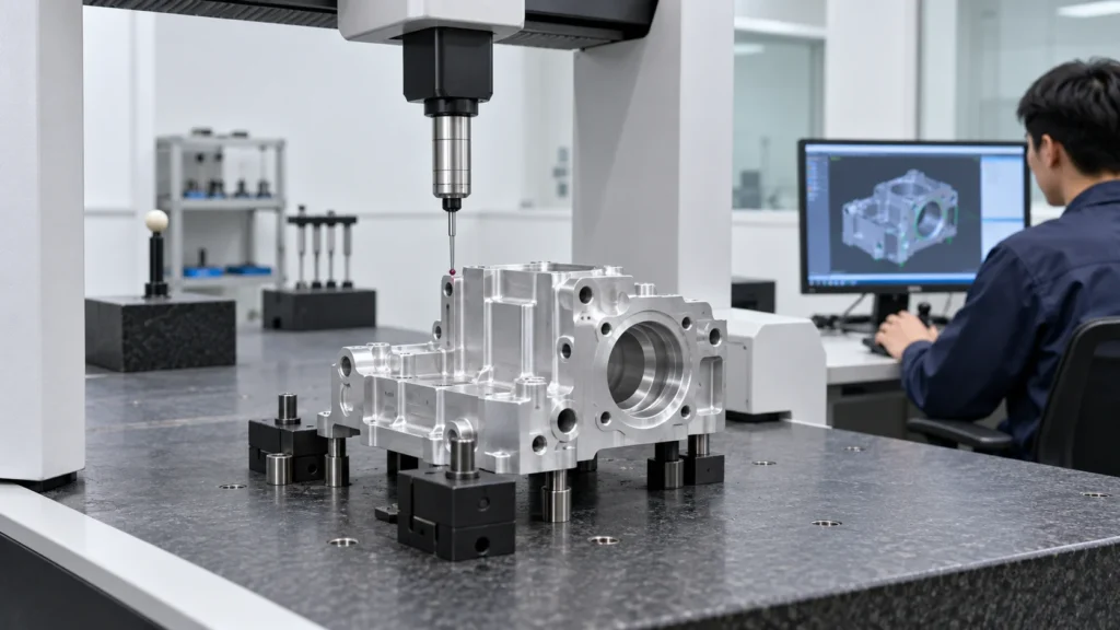
Which milling features usually need special attention?
- Datum faces and their relationship to the inspection coordinate system.
- Hole location, diameter, depth, thread condition, counterbore, and countersink.
- Pocket floor depth, wall position, internal corner radius, and remaining wall thickness.
- Flatness, perpendicularity, parallelism, profile, and the relationship between multiple setups.
- Thin walls, flexible ribs, sealing surfaces, and features that may move after unclamping.
- Surface roughness, burr condition, cleanliness, coating allowance, and cosmetic zones where specified.
Manual gauges may be suitable for straightforward dimensions. Probing, height measurement, optical inspection, or CMM measurement may be selected when geometry and tolerance relationships require more evidence. The measurement method must match the characteristic; a CMM report is not automatically meaningful if the drawing revision, datums, or evaluation method are unclear.
When supplier quality documentation matters, review the CNC quality management information and define the exact reports required for the project. Quality expectations should be tied to the drawing and application rather than expressed only as “high precision.”
Entregue al socio de mecanizado un paquete de RFQ utilizable
A milling quotation becomes more accurate when the supplier can see the design intent, not just the solid model. Provide the current 3D CAD file and controlled 2D drawing together, then identify the information that changes the process route:
- Part identity: part number, revision, quantity, forecast, and prototype or production status.
- Material: exact grade, condition, hardness where relevant, certification, and any fluid or temperature exposure.
- Feature requirements: datums, fits, hole and thread specifications, critical profiles, thin walls, and sealing surfaces.
- Finish: surface roughness, appearance zones, masking, anodizing, plating, passivation, polishing, or other secondary work.
- Inspección: first article requirements, critical dimensions, CMM or gauge reports, sampling, traceability, and acceptance criteria.
- Delivery: target window, packaging, destination, repeat-order expectations, and any release documentation.
Explain what the part must do when a feature is difficult to interpret from geometry alone. That context helps the manufacturing engineer decide whether a different cutter, workholding method, axis strategy, material condition, staged inspection, or secondary process is justified. It also makes supplier quotations easier to compare because the assumptions are visible.
Preguntas frecuentes sobre el proceso de fresado CNC
What is the CNC milling process used for?
The CNC milling process is used to remove material from a fixed or securely located workpiece with rotating cutting tools. It is well suited to faces, pockets, slots, holes, ribs, bosses, angled surfaces, and three-dimensional profiles in metals and engineering plastics.
When is 5-axis milling better than 3-axis milling?
5-axis milling is worth evaluating when a part has multiple compound faces, difficult tool access, sculpted surfaces, or several features that would otherwise require repeated setups. It is not automatically better for a simple prismatic part; geometry, fixture design, tolerance relationships, programming, and inspection determine the benefit.
How many setups does a milled part need?
Setup count depends on feature access, datum structure, workholding, part stiffness, and the required inspection relationships. One setup may be ideal for accessible features, while a housing or multi-sided component may need several planned orientations or a multi-axis strategy. Fewer setups are valuable only when the part remains securely located and measurable.
Does CNC milling always produce the tightest tolerance?
No. Achievable tolerance depends on feature size, material, geometry, tool reach, machine condition, workholding, thermal behavior, inspection method, and production quantity. A tolerance should describe the function of the feature, and the process should be selected to control the complete relationship rather than one isolated dimension.
What should buyers ask before approving a milling quote?
Ask which machine and axis strategy are planned, how the part will be located, how many setups are required, which features are critical, what material condition is assumed, how surfaces will be finished, and which inspection documents will be supplied. Clear assumptions make price, lead time, and technical risk easier to compare.
Effective milling is a controlled chain from functional feature definition to tool access, workholding, material behavior, cutting strategy, and inspection. When those decisions are made together, engineers can choose the simplest process that protects the part’s real requirements and gives production a repeatable path to follow.