
Processus de fraisage CNC la planification doit commencer par les caractéristiques fonctionnelles de la pièce, et non par un catalogue de machines. Les poches, les trous, les nervures, les faces inclinées, les parois minces, les références et les surfaces esthétiques imposent chacune des exigences différentes en matière d'accès de l'outil, de maintien en position, de mouvement des axes et d'inspection. Ce guide explique comment les ingénieurs et les acheteurs peuvent transformer un dessin en une gamme de fraisage pratique, quand l'usinage 3 axes, 4 axes ou 5 axes est pertinent, et quelles décisions préservent l'ajustement et la répétabilité. Pour la séquence de fabrication plus large, voir l' Aperçu du processus d'usinage CNC.
Commencer par les caractéristiques fonctionnelles de la pièce
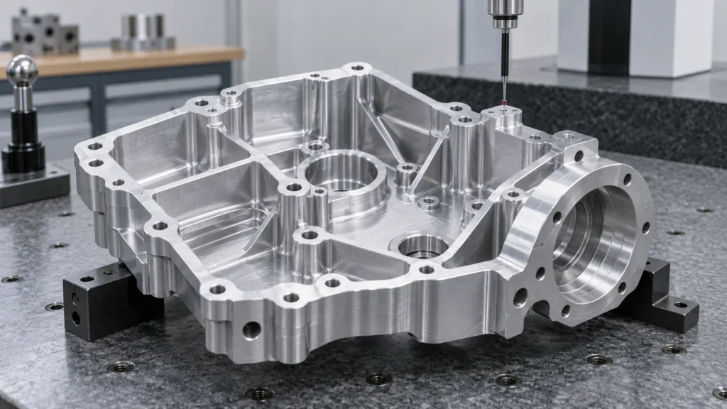
Un plan de fraisage utile commence par séparer la pièce en groupes de caractéristiques fonctionnelles :
- Références et faces de localisation : surfaces qui établissent la référence d'inspection et d'assemblage de la pièce.
- Caractéristiques d'enlèvement de matière : poches, rainures, épaulements, nervures, bossages et profils extérieurs.
- Caractéristiques de liaison : trous de boulons, trous de goujons, trous taraudés, lamages et schémas de montage.
- Surfaces fonctionnelles : faces d'étanchéité, portées de roulements, faces de glissement, interfaces thermiques et plots d'alignement.
- Caractéristiques sensibles à l'accès : cavités profondes, canaux étroits, contre-dépouilles, parois inclinées et petits rayons internes.
- Zones sensibles à l'aspect : faces visibles où les marques d'outil, bavures, rayures ou textures irrégulières comptent.
La classification des caractéristiques modifie le procédé. Une poche qui ne fait que réduire le poids peut tolérer une stratégie différente d'une poche qui localise un roulement. Un trou utilisé pour un goujon nécessite un plan d'inspection différent d'un trou de passage. Traiter chaque surface comme une cible d'usinage de priorité égale crée souvent des coûts inutiles tout en laissant les relations vraiment importantes sous-définies.
Établir une carte des caractéristiques avant de choisir les outils
Une carte des caractéristiques relie l'intention du dessin aux actions physiques requises sur la machine. Elle doit montrer quelles surfaces doivent être créées en premier, quelles caractéristiques nécessitent un support et quelles dimensions dépendent du même montage. C'est à ce stade qu'un ingénieur de fabrication peut identifier une pile de tolérances cachée avant qu'elle ne devienne un problème en atelier.
Quelles caractéristiques doivent partager un même montage ?
Les caractéristiques qui doivent rester alignées doivent être usinées à partir de la même référence de datum chaque fois que cela est possible. Par exemple, un motif d'alésages et sa face de montage environnante peuvent être plus fiables lorsqu'ils sont produits sans perdre le repère d'usinage principal. Déplacer la pièce vers un autre montage peut introduire une erreur de positionnement, une variation de serrage et une nouvelle occasion pour les copeaux ou les bavures d'affecter l'appui.
Plusieurs montages sont parfois nécessaires. Les pièces hautes, les boîtiers à cinq faces, les poches profondes et les caractéristiques cachées derrière une paroi peuvent nécessiter une séquence planifiée. L'objectif n'est pas de minimiser le nombre de montages à tout prix ; l'objectif est de minimiser les transferts de datum non contrôlés tout en maintenant l'accès aux outils et la stabilité du maintien de la pièce.
Où la géométrie et l'accès aux outils entrent-ils en conflit ?
Les angles internes, la profondeur des poches, la hauteur des parois et les petits trous peuvent imposer un compromis entre la géométrie demandée et un outil rigide et économique. Un angle interne étroit peut nécessiter un outil plus petit, une plus grande portée, une coupe plus lente ou un procédé alternatif. Les poches profondes peuvent être usinées, mais le rapport portée/diamètre, l'évacuation des copeaux, les vibrations et l'accès pour l'inspection font partie du devis.
Un bon retour DFM n'efface pas l'intention de conception. Il identifie quelles dimensions sont fonctionnelles, lesquelles peuvent utiliser un rayon pratique et quelles surfaces nécessitent un procédé spécial. Cette distinction aide l'acheteur à approuver un changement sur la base de la valeur technique plutôt que sur une demande vague de “ rendre les choses plus faciles ”.”
Transformer la carte des caractéristiques en un plan de fraisage
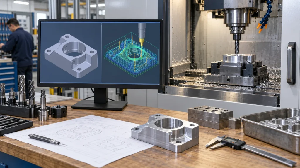
Que doit protéger la séquence d'usinage ?
La séquence doit protéger les surfaces de positionnement stables, préserver suffisamment de matière pour la finition et empêcher une opération d'endommager une caractéristique qui sera utilisée ultérieurement. Un itinéraire courant commence par le surfaçage ou la création de références, se poursuit par l'enlèvement de matière en masse, puis passe à la semi-finition et aux passes finales. Les trous, les filetages, les parois minces et les surfaces critiques sont placés en fonction du support, de l'accès, de la direction des bavures et des besoins de mesure.
La vérification des trajectoires d'outils doit contrôler le dégagement du porte-outil, la portée de l'outil, le risque de collision, la matière restante, les déplacements rapides et la direction d'engagement de la matière. La simulation réduit les erreurs de programmation évitables, mais elle ne remplace pas une vérification physique de la rigidité du montage, du faux rond de l'outil, de l'état de la matière, de l'amenée du liquide de refroidissement et de l'évacuation des copeaux.
En quoi l'ébauche doit-elle différer de la finition ?
L'ébauche est organisée autour d'un enlèvement de matière sûr et efficace. La finition est organisée autour de la géométrie, de l'état de surface et de la stabilité de l'outil. Laisser une surépaisseur prévisible pendant l'ébauche donne à l'outil de finition un engagement constant. Enlever trop de matière d'un coup peut augmenter la chaleur et la déflexion ; laisser une surépaisseur irrégulière ou instable peut rendre la dernière passe imprévisible.
Les plans d'usinage doivent également tenir compte de la matière résiduelle dans les angles internes et les transitions. Des outils plus petits peuvent être nécessaires pour le nettoyage local, mais les utiliser sur toute la pièce peut augmenter le temps de cycle et le risque de casse. Un processus équilibré utilise le plus grand outil rigide pratique pour le travail en masse et réserve les outils plus petits aux caractéristiques qui en ont réellement besoin.
Choisir la stratégie d'axes selon l'accès, non selon le prestige
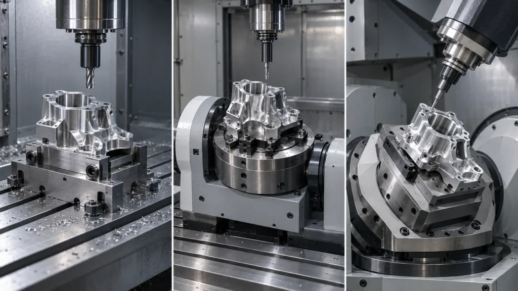
| Axis approach | Useful when | Main planning question |
|---|---|---|
| 3-axis | Prismatic parts, open pockets, planar faces, and accessible contours | Can the part be located rigidly while the cutter reaches every critical feature? |
| 4-axis or indexed rotary | Features distributed around a part or repeated angular positions | Will rotary indexing reduce setups without weakening the locating scheme? |
| 5-axis | Compound angles, multiple faces, sculpted surfaces, and access-sensitive geometry | Will tool orientation and fewer setups improve access, accuracy, or surface control enough to justify the route? |
A 5-axis machine is not automatically the right answer. A simple plate may be faster and easier to inspect on a 3-axis center. A complex housing may benefit from fewer setups, but only if the machine, fixture, post-processor, and inspection plan are coordinated. Review the 5-axis milling capability as part of the process comparison, then make the final decision from the part’s access and tolerance requirements.
Adapter les opérations de fraisage à la matière restante
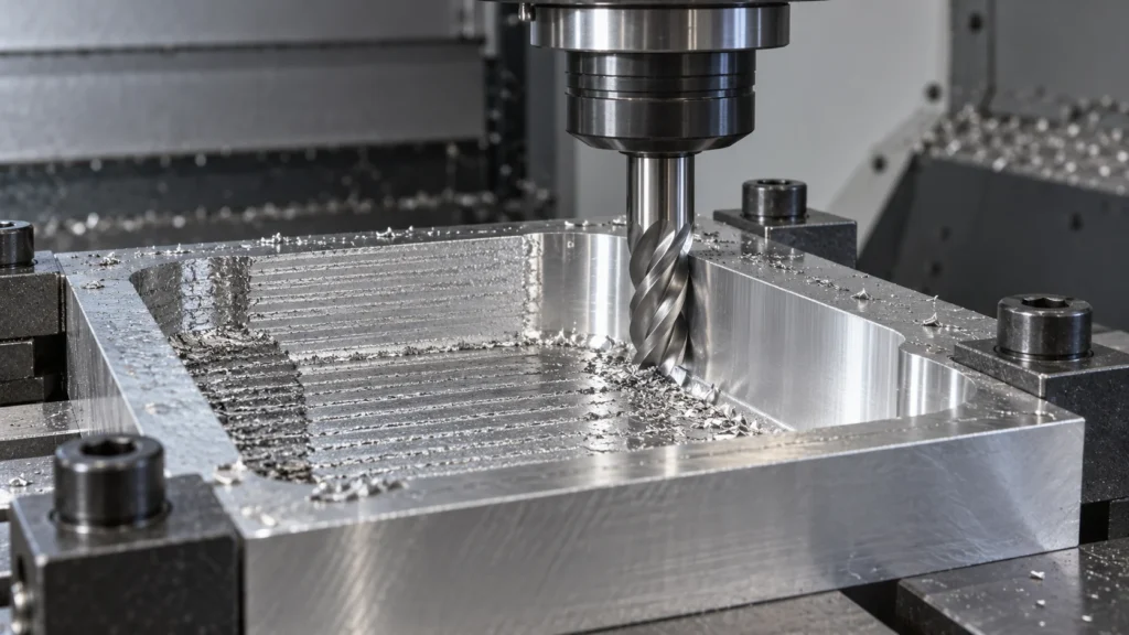
Which operation fits a common feature?
- Facing: creates a reference plane or removes stock from a broad surface.
- Pocketing: removes internal material while controlling floor, wall, corner, and chip-evacuation conditions.
- Contouring: follows an outside or inside profile where wall location and edge condition matter.
- Slotting: creates a narrow channel but may require attention to full-width engagement, deflection, and chip packing.
- Drilling and boring: establish or refine holes according to diameter, depth, position, fit, and surface needs.
- Thread milling: produces internal or external threads when the geometry and material make it useful.
- 3D finishing: controls scallop height, tool orientation, and surface continuity on curved or angled faces.
These operations are building blocks rather than a universal recipe. A deep pocket may need a roughing path, a rest-machining path, a semi-finish pass, and a final wall or floor pass. A thin rib may require the surrounding material to remain as support until late in the sequence. A finish requirement should be connected to a measurable specification, not added as an isolated promise after the toolpath is complete.
How do toolpaths affect surface and cycle time?
CNC milling toolpaths control how much material a cutter engages, how often the tool changes direction, and how the cutting load moves through the part. Roughing strategies prioritize stable removal and chip evacuation. Finishing strategies prioritize consistent engagement, step-over, tool orientation, and the direction of visible marks.
A shorter toolpath is not always the lower-risk toolpath. Aggressive engagement can reduce theoretical cycle time while increasing tool wear, chatter, heat, or rework. The useful target is a repeatable process with a predictable inspection result, not the fastest first-piece cut.
Préserver l'intégrité des références lors de la mise en position
A stable program can still produce a misplaced part when the physical setup is weak. CNC milling setup planning defines the stock orientation, work coordinate system, fixture, clamps, tool offsets, probing, and first-piece checks. The setup should restrain movement without distorting thin walls, sealing faces, or flexible plastic features.
What makes CNC milling workholding reliable?
Reliable CNC milling workholding locates the part from surfaces that reflect the drawing’s datum structure and supports the cutting forces created by the toolpath. Clamps should not obstruct critical access, create avoidable marks, or load a thin section so heavily that the part moves after release.
Multi-sided parts may need soft jaws, a fixture plate, modular locating, or a planned sequence of reorientations. Each additional setup should have a defined reason: access, support, inspection, or a required manufacturing feature. Re-clamping without a controlled locating method turns a dimensional requirement into an operator-dependent result.
When should probing be included?
Probing can help establish work coordinates, verify stock location, check selected features, and detect setup variation before a full run. It is most useful when connected to a defined control plan. Probing is not a substitute for a final inspection method, and it should not be treated as proof that every tolerance on the drawing has been measured.
Laisser le comportement de la matière définir les conditions de coupe
Material choice changes the milling route. Aluminum, stainless steel, titanium, brass, engineering plastics, and high-temperature materials differ in hardness, thermal behavior, chip formation, burr tendency, stiffness, and sensitivity to clamping. Material grade and condition should be confirmed before the process is quoted, not after a toolpath has already been selected.
| Material behavior | Milling concern | Réponse de planification |
|---|---|---|
| High ductility or gummy chips | Built-up edge, burrs, and chip packing | Use suitable sharp tooling, chip evacuation, coolant, and edge-control planning |
| High hardness or work hardening | Tool wear, heat, and unstable engagement | Control tool engagement, rigidity, cutting conditions, and tool life |
| Low stiffness or thermal sensitivity | Deflection, deformation, and dimensional drift | Reduce clamping distortion, shorten tool reach, and plan staged removal and inspection |
Use the site’s CNC milling materials page as a starting point for material-route discussions, then confirm the exact grade, condition, finish, and certification requirements in the RFQ. Cutting speed, feed, depth of cut, radial engagement, tool diameter, and coolant are process variables; they should not be presented as universal numbers without the machine, tool, material, and geometry context.
Savoir quand le fraisage n'est pas la meilleure solution
A professional process plan includes the option not to mill a feature in the same way as the rest of the part. Rotational geometry may be more efficient on a turning center. A part with both turned and milled features may benefit from turn-mill machining when additional setups would threaten alignment. Certain conductive profiles or hardened features may call for Wire EDM, while selected precision surfaces may be finished by grinding.
Process selection should consider geometry, material, quantity, tolerance, surface requirements, setup risk, and inspection. Choosing 5-axis milling for a part that does not need its access can add programming and fixture complexity. Choosing 3-axis milling for a part that needs repeated reorientation can create datum-transfer risk. The right route is the one that delivers the required features with controlled evidence.
This boundary matters for buyers because a quotation is more useful when it explains its assumptions. Ask which features are milled, which require secondary operations, how many setups are planned, and which dimensions will be verified at each stage.
Vérifier les caractéristiques qui font fonctionner la pièce
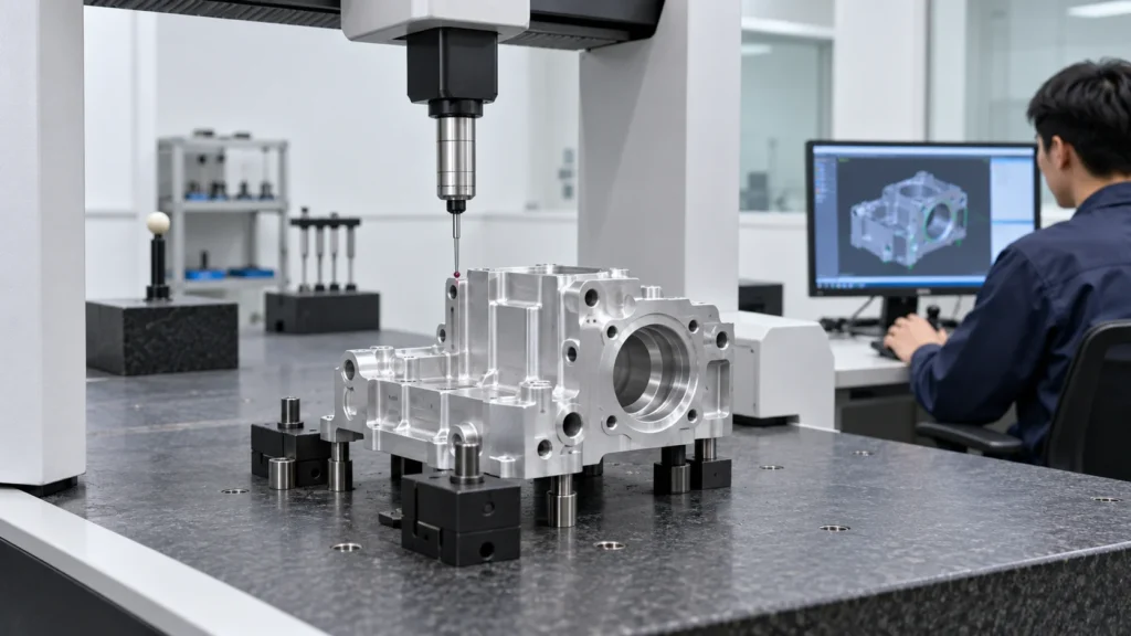
Which milling features usually need special attention?
- Datum faces and their relationship to the inspection coordinate system.
- Hole location, diameter, depth, thread condition, counterbore, and countersink.
- Pocket floor depth, wall position, internal corner radius, and remaining wall thickness.
- Flatness, perpendicularity, parallelism, profile, and the relationship between multiple setups.
- Thin walls, flexible ribs, sealing surfaces, and features that may move after unclamping.
- Surface roughness, burr condition, cleanliness, coating allowance, and cosmetic zones where specified.
Manual gauges may be suitable for straightforward dimensions. Probing, height measurement, optical inspection, or CMM measurement may be selected when geometry and tolerance relationships require more evidence. The measurement method must match the characteristic; a CMM report is not automatically meaningful if the drawing revision, datums, or evaluation method are unclear.
When supplier quality documentation matters, review the CNC quality management information and define the exact reports required for the project. Quality expectations should be tied to the drawing and application rather than expressed only as “high precision.”
Fournir au partenaire d'usinage un dossier RFQ exploitable
A milling quotation becomes more accurate when the supplier can see the design intent, not just the solid model. Provide the current 3D CAD file and controlled 2D drawing together, then identify the information that changes the process route:
- Part identity: part number, revision, quantity, forecast, and prototype or production status.
- Material: exact grade, condition, hardness where relevant, certification, and any fluid or temperature exposure.
- Feature requirements: datums, fits, hole and thread specifications, critical profiles, thin walls, and sealing surfaces.
- Finish: surface roughness, appearance zones, masking, anodizing, plating, passivation, polishing, or other secondary work.
- Inspection: first article requirements, critical dimensions, CMM or gauge reports, sampling, traceability, and acceptance criteria.
- Delivery: target window, packaging, destination, repeat-order expectations, and any release documentation.
Explain what the part must do when a feature is difficult to interpret from geometry alone. That context helps the manufacturing engineer decide whether a different cutter, workholding method, axis strategy, material condition, staged inspection, or secondary process is justified. It also makes supplier quotations easier to compare because the assumptions are visible.
FAQ sur le processus de fraisage CNC
What is the CNC milling process used for?
The CNC milling process is used to remove material from a fixed or securely located workpiece with rotating cutting tools. It is well suited to faces, pockets, slots, holes, ribs, bosses, angled surfaces, and three-dimensional profiles in metals and engineering plastics.
When is 5-axis milling better than 3-axis milling?
5-axis milling is worth evaluating when a part has multiple compound faces, difficult tool access, sculpted surfaces, or several features that would otherwise require repeated setups. It is not automatically better for a simple prismatic part; geometry, fixture design, tolerance relationships, programming, and inspection determine the benefit.
How many setups does a milled part need?
Setup count depends on feature access, datum structure, workholding, part stiffness, and the required inspection relationships. One setup may be ideal for accessible features, while a housing or multi-sided component may need several planned orientations or a multi-axis strategy. Fewer setups are valuable only when the part remains securely located and measurable.
Does CNC milling always produce the tightest tolerance?
No. Achievable tolerance depends on feature size, material, geometry, tool reach, machine condition, workholding, thermal behavior, inspection method, and production quantity. A tolerance should describe the function of the feature, and the process should be selected to control the complete relationship rather than one isolated dimension.
What should buyers ask before approving a milling quote?
Ask which machine and axis strategy are planned, how the part will be located, how many setups are required, which features are critical, what material condition is assumed, how surfaces will be finished, and which inspection documents will be supplied. Clear assumptions make price, lead time, and technical risk easier to compare.
Effective milling is a controlled chain from functional feature definition to tool access, workholding, material behavior, cutting strategy, and inspection. When those decisions are made together, engineers can choose the simplest process that protects the part’s real requirements and gives production a repeatable path to follow.