
Introduction : Le rôle critique de la précision dans l'usinage des boîtiers d'actionneurs
Dans le monde du contrôle du mouvement, où les bras robotisés exécutent des mouvements inférieurs au millimètre et où les surfaces de vol des aéronefs s'ajustent avec une fiabilité vitale, le héros méconnu est souvent le boîtier d'actionneur. Cette enveloppe structurelle est bien plus qu'un simple contenant ; c'est le châssis fondamental qui dicte les performances, la longévité et la sécurité de l'ensemble du système d'actionnement. L'usinage de ce composant n'est pas une étape de fabrication secondaire—c'est un défi d'ingénierie primordial où la précision n'est pas négociable. Un écart de quelques microns dans le diamètre d'un alésage ou un léger déséquilibre dans l'épaisseur de paroi peut entraîner une usure prématurée des roulements, un désalignement des engrenages internes, un fonctionnement inefficace du moteur ou une défaillance structurelle catastrophique sous charge. Dans des industries comme l'aérospatiale et la robotique, la marge d'erreur approche de zéro, ce qui fait du choix du partenaire de fabrication et du processus une décision qui impacte directement l'innovation et l'intégrité opérationnelle. Cet article explore le monde complexe de l'usinage de boîtiers d'actionneurs, l'usinage des boîtiers d'actionneurs, en examinant les matériaux, les processus avancés et l'accent incessant mis sur la qualité qui transforment le métal brut en colonne vertébrale de l'automatisation moderne.
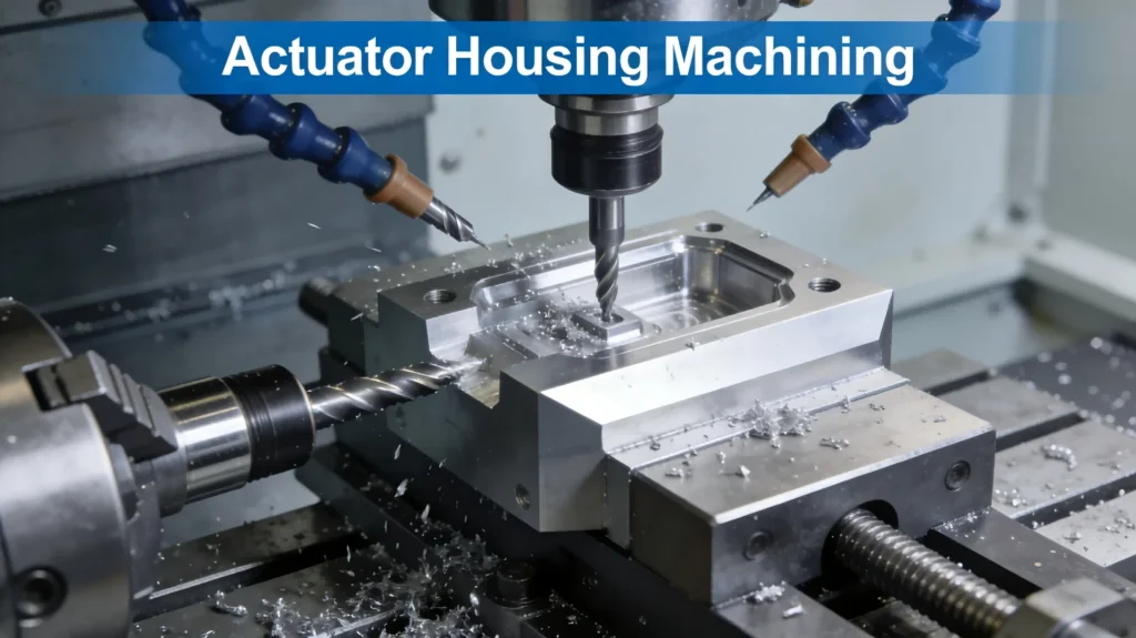
Qu'est-ce que l'usinage de boîtier d'actionneur ? Définition du composant central
Un boîtier d'actionneur est l'enceinte usinée de précision qui contient et protège les composants essentiels d'un actionneur—le moteur, les engrenages, les vis à billes, les roulements et les capteurs de rétroaction. Considérez-le comme le squelette et l'armure du système. Ses fonctions principales sont multiples : il fournit un support structurel rigide pour maintenir un alignement parfait de toutes les pièces mobiles, gère les charges thermiques en dissipant la chaleur du moteur et de l'électronique, offre une étanchéité environnementale contre les contaminants comme la poussière et l'humidité, et intègre souvent des interfaces de montage complexes pour une intégration facile dans des ensembles plus grands comme une articulation de robot ou une aile d'aéronef.
Le processus d'usinage est ce qui transforme un bloc forgé ou une pièce coulée en métal en ce composant sophistiqué. Il implique l'enlèvement systématique de matière à l'aide d'outils de coupe contrôlés par ordinateur pour créer des caractéristiques géométriques spécifiques. Ces caractéristiques comprennent des alésages de précision pour les roulements, des ports filetés pour les capteurs et la lubrification, des contours complexes pour la réduction de poids et la circulation du liquide de refroidissement, et des surfaces d'étanchéité méticuleusement planes. La complexité des boîtiers modernes, qui intègrent souvent plusieurs fonctions dans une unité unique et compacte pour économiser l'espace et le poids, pousse l'usinage conventionnel à ses limites. C'est pourquoi définir l'usinage de boîtier d'actionneur simplement comme “ fabriquer une boîte ” est un euphémisme profond. C'est la création d'un écosystème mécanique multifonctionnel à haute tolérance où chaque surface interne et chaque bride externe joue un rôle critique dans la performance finale du système.
Matériaux clés pour les boîtiers d'actionneurs : des alliages d'aluminium aux composites avancés
La sélection du matériau pour un boîtier d'actionneur est une décision fondamentale qui équilibre la résistance, le poids, les propriétés thermiques, l'usinabilité et le coût. Le bon choix est dicté par les exigences opérationnelles de l'application.
Alliages d'aluminium : le cheval de trait pour une performance légère
Les alliages d'aluminium, en particulier la série 6000 comme le 6061-T6, sont le choix le plus répandu pour une large gamme d'applications, de la robotique industrielle à l'e-mobilité. Comme souligné dans notre base de connaissances, le 6061-T6 offre un “ équilibre optimal entre les propriétés de légèreté et la résistance structurelle—essentiel pour les modules de mouvement robotiques qui nécessitent à la fois agilité et capacité de charge. ” Son excellente usinabilité permet des taux d'enlèvement de matière élevés et la création de caractéristiques complexes à parois minces avec un bon état de surface. De plus, l'aluminium dissipe naturellement la chaleur efficacement, une propriété cruciale pour les boîtiers contenant des moteurs électriques. Pour les applications exigeant des rapports résistance-poids encore plus élevés, comme dans la robotique haute performance ou l'aérospatiale, l'alliage d'aluminium 7075 est souvent spécifié, bien qu'il puisse être plus difficile à usiner.
Aciers inoxydables et aciers alliés : pour la résistance et la durabilité
Lorsque l'application implique des charges extrêmes, une résistance élevée aux chocs ou un fonctionnement dans des environnements corrosifs, les aciers inoxydables (comme le 304 ou le 316) et les aciers alliés (comme le 4140) sont sélectionnés. Ces matériaux offrent une résistance à la traction et une dureté supérieures à celles de l'aluminium. Ils sont courants dans l'automatisation industrielle lourde, les applications marines et les systèmes d'actionnement aérospatiaux où la fiabilité sous contrainte est primordiale. Cependant, cette résistance s'accompagne de compromis : un poids accru et une plus grande difficulté d'usinage, ce qui peut impacter le temps de production et les coûts d'outillage.
Composites avancés et titane : repousser les limites
À la pointe de la performance, notamment dans l'aérospatiale et le sport automobile haut de gamme, des matériaux comme le titane et les composites avancés entrent en jeu. Le titane offre un rapport résistance-poids phénoménal et une résistance exceptionnelle à la corrosion, ce qui le rend idéal pour les systèmes d'actionneurs aéroportés les plus exigeants. L'usinage du titane est un art spécialisé, nécessitant des vitesses lentes, une grande rigidité et un outillage avancé pour gérer la chaleur et prévenir l'écrouissage. Les composites, bien que moins couramment usinés en boîtiers complets, sont de plus en plus utilisés pour certains composants ou comme revêtement pour réduire le poids sans sacrifier la rigidité. L'usinage de ces matériaux non métalliques nécessite des techniques entièrement différentes, telles que l'outillage à revêtement diamanté et l'extraction spécialisée de poussière, pour atteindre la précision requise sans délaminage ni effilochage.
The choice is never made in isolation. As referenced in the knowledge base from MAPAL, the material’s behavior during “large-scale series production” is a key factor. Cast aluminum housings, for instance, may have draft angles and inconsistent stock, requiring tooling and processes robust enough to handle significant material variation while still holding tight tolerances.
Core Machining Processes: CNC Turning, Milling, and 5-Axis Contouring
The creation of a precision actuator housing is a symphony of coordinated machining operations. Each process is selected based on the geometric feature being produced, with the goal of achieving maximum accuracy and surface integrity in the most efficient sequence.
CNC Turning: Mastering Rotational Symmetry
CNC turning is the go-to process for features that are radially symmetrical about a central axis. Performed on a lathe, where the workpiece rotates and a stationary cutting tool removes material, turning is ideal for machining the outer diameters, facing ends to create flat sealing surfaces, and boring precise internal diameters (IDs) of cylindrical housings or sub-sections. For actuator housings, turning is critical for creating the main bearing journals and motor mount bores, where concentricity and surface finish are vital for smooth rotation and long service life. Many complex housings start as a turned blank before moving to a milling machine for additional features.
CNC Milling: The Art of Three-Dimensional Contouring
CNC milling is the versatile workhorse for creating the majority of an actuator housing’s geometry. A rotating cutting tool moves along multiple linear axes (X, Y, Z) to machine flat faces, slots, pockets, and complex contours. As described in the product specification for a robotic linear actuator housing, “CNC Vertical Milling (including drilling, tapping, and precision hollow milling)” is employed to create the structural frame, mounting bosses, and internal cavities. Milling operations define the housing’s external shape, machine the interfaces for gear trains, and create the network of threaded holes (tapping) for assembling internal components and external covers. The precision of these features, with hole position tolerances as tight as ±0.01 mm, is what ensures seamless assembly and optimal function of the actuator.
5-Axis Contouring: Unlocking Unprecedented Geometric Freedom
For the most complex actuator housings, 3-axis milling reaches its limitations. This is where 5-axis CNC machining becomes a game-changer. A 5-axis machine can move the cutting tool or the workpiece along five different axes simultaneously (three linear and two rotational). This capability allows the tool to approach the workpiece from virtually any angle in a single setup. The advantages for actuator housing machining are profound. First, it enables the “simultaneous 5-axis contouring of helical gear teeth and other complex internal geometries” directly into the housing, as noted in the case study on robotic actuator housings. This eliminates the need for secondary operations and guarantees perfect alignment. Second, it allows for the machining of undercuts, angled ports, and sculpted surfaces that are impossible with a 3-axis approach. Third, by completing the vast majority of the part in one clamping, as seen with the Mori Seiki NMV3000 machining a complex housing in a “single operation,” it eliminates errors that can accumulate from moving and re-fixturing the part between setups. This single-setup machining is critical for maintaining the ultra-tight tolerances and positional accuracies required in high-performance applications.
These core processes are rarely used in isolation. A typical high-precision housing will undergo a carefully orchestrated sequence: rough turning or milling to remove bulk material, semi-finishing, and then a final finishing pass with specialized toolpaths to achieve the final dimensions and surface quality. Throughout, considerations like thermal management (to prevent part distortion from machining heat) and thin-wall machining strategies (to prevent chatter and deflection) are paramount, setting the stage for the high-tolerance challenges that define this field.
Overcoming High-Tolerance Challenges: Precision, Thermal Management, and Thin Walls
The orchestrated sequence of core machining processes culminates in confronting the most demanding aspects of l'usinage de boîtiers d'actionneurs: achieving micron-level precision while managing thermal effects and structural fragility. These challenges are not isolated; they are interconnected puzzles that must be solved simultaneously to produce a housing that meets stringent functional specifications.
Precision in this context extends beyond simple dimensional accuracy. It encompasses geometric tolerances like concentricity, perpendicularity, and true position of bearing seats, sensor mounts, and gear interfaces. A deviation of a few microns in the alignment of a bearing bore can lead to premature wear, increased friction, and catastrophic failure in a high-speed robotic or aerospace actuator. The references highlight that maintaining such precision requires a holistic approach, starting with machine tool rigidity and thermal stability, extending to toolpath strategies that minimize tool deflection and adaptive control systems that compensate for tool wear in real-time.
Thermal management is a dual-front battle. First, there is the heat generated by the cutting process itself. Uncontrolled, this heat transfers into the workpiece, causing localized thermal expansion that distorts the part during machining. When the part cools, it contracts, leading to out-of-tolerance dimensions. Strategies to combat this include using high-pressure coolant systems that precisely target the cutting edge, employing trochoidal or peel milling techniques that reduce heat buildup by keeping the tool in constant, light engagement, and allowing for thermal stabilization periods between roughing and finishing operations. Second, for housings that will enclose electric motors or high-performance gearboxes, the design often incorporates integrated cooling channels. Machining these thin, winding internal passages without breaking through the housing wall adds another layer of complexity, often requiring specialized tooling and precise control of drilling depths and angles.
Perhaps the most visually delicate challenge is machining thin walls. As noted in the e-mobility context, electric motor housings often feature thin walls for weight reduction and to accommodate cooling channels, making them prone to natural oscillation and distortion under machining forces. The “bell-like shape” mentioned is a classic example. The solution lies in a combination of intelligent fixturing, toolpath optimization, and tool selection. Fixturing must support the part uniformly to dampen vibration without inducing clamping distortion. Toolpaths are programmed to take light, finishing passes with sharp tools, often climbing mill to push the thin wall against the solid material behind it rather than pulling it away. Specialized tools with high rake angles and variable helix designs are used to shear the material cleanly with minimal radial force, preventing chatter—a destructive vibration that can ruin surface finish and dimensional accuracy.
The 5-Axis CNC Advantage for Complex Actuator Housing Geometries
When the challenges of precision, thermal management, and thin walls are combined with highly complex, organic geometries, the limitations of 3-axis machining become apparent. This is where 5-axis CNC machining transitions from an advantage to a necessity. The ability to manipulate the cutting tool or the workpiece along five axes simultaneously unlocks the capability to machine intricate features in a single, streamlined setup.
The primary benefit is unparalleled access. Complex housings for robotics or aerospace often feature deep cavities, undercuts, and compound angles that are simply unreachable with a standard 3-axis mill. A 5-axis machine can tilt and rotate the spindle or the part to orient the cutting tool perpendicular to the surface being machined, even if that surface is on the side of a deep pocket or at a steep angle. This is critical for features like the helical gear teeth mentioned in the robotic actuator case, where the tool must follow a complex, twisting path to accurately form the gear profile. With 3-axis machining, this would require multiple specialized fixtures and setups, each introducing potential alignment errors.
Beyond access, 5-axis contouring enables superior surface finish and accuracy on complex curves. By maintaining the optimal cutting angle (tool lead and tilt) relative to the contoured surface, the machine uses the side of the end mill more effectively than the tip, which improves finish and extends tool life. This “simultaneous 5-axis contouring” allows for the smooth machining of aerodynamic surfaces on aerospace housings or the ergonomic, sculpted forms found in advanced robotic joints. The Mori Seiki NMV3000 example, which completes a complex part in a “single operation,” is a testament to this capability. By eliminating multiple setups, it ensures that all features are machined in perfect spatial relationship to one another, directly addressing the high-tolerance positional accuracy requirements.
Furthermore, 5-axis machining can often use shorter, more rigid cutting tools because the head can be tilted to reach into areas that would otherwise require a long, flexible tool prone to deflection. Reduced tool deflection means more consistent cuts, better surface finishes, and the ability to hold tighter tolerances, especially on deep features. This integrated approach consolidates what was once a multi-machine, multi-setup job into a single, highly efficient process, reducing lead time, labor, and the cumulative error stack-up that is the enemy of ultra-high precision.
From Prototype to Production: Scalability and Process Optimization
The journey from a validated prototype to reliable, cost-effective volume production is a critical phase in actuator housing manufacturing. The strategies that work for one-off or low-volume parts often do not scale efficiently. The transition demands a deliberate shift in focus from pure capability to optimized, repeatable process control.
In prototype and low-volume runs, the priority is flexibility and speed to market. Machining might utilize more generalized tooling and conservative, safe toolpaths to ensure the part is made correctly the first time. However, as volumes scale—particularly in industries like automotive e-mobility—every second of cycle time and every tool change has a magnified impact on unit cost. Here, process optimization becomes paramount. This involves designing dedicated, multi-function tooling, like the custom fine boring tools with welded designs mentioned by MAPAL for electric motor housings. These tools consolidate multiple operations (e.g., pre-machining, semi-finishing, and fine machining of a stator bore) into one, reducing non-cut time and improving accuracy.
Scalability also demands a rigorous analysis of the entire machining sequence for efficiency gains. For high-volume electric motor housing production, the process is broken down into stages: pre-machining the complex contour, then finishing the complete contour including critical bearing and stator bores. Each stage is optimized for speed and tool life. Chip management, often an afterthought in prototyping, becomes a critical concern; broken and efficiently evacuated chips are essential for uninterrupted production. The references note the use of special chip guiding stages and chip breaker geometries to ensure process-reliable chip breakage and removal in high-volume settings.
Another key aspect of scalability is designing for manufacturability (DFM) feedback loops. A close partnership between the design engineer and the manufacturing partner allows for subtle design modifications that dramatically improve producibility without compromising function. This might involve adjusting a corner radius to allow for a standard cutter size, adding a slight draft to a wall to facilitate tool access, or specifying tolerances that align with high-volume process capabilities. The goal is to create a production process that is not only fast and accurate but also robust—capable of running thousands of parts with minimal intervention and consistent quality, a necessity highlighted by the automotive industry’s move into large-scale electric motor production.
Quality Control and Inspection: Ensuring Actuator Housing Integrity
In high-stakes applications, the integrity of an actuator housing is non-negotiable. A comprehensive quality control (QC) and inspection regimen is the final, essential gatekeeper, verifying that every challenge of machining has been successfully overcome and that the part conforms to all design specifications. This goes far beyond a simple final check; it is an integrated philosophy that spans the entire manufacturing process.
First Article Inspection (FAI) is a critical starting point. When a new part is introduced or a process is significantly changed, every dimension and tolerance on the drawing is meticulously verified using high-precision equipment like Coordinate Measuring Machines (CMM). This creates a baseline and validates the manufacturing process. For production runs, statistical process control (SPC) takes over. Key characteristics—such as the diameter of a critical bearing bore or the true position of mounting holes—are measured at defined intervals. The data is charted to identify trends toward tolerance limits before any non-conforming parts are produced, allowing for proactive machine adjustment.
The tools of modern inspection are as advanced as the machining centers themselves. CMMs with touch-triggers or laser scanners can quickly and accurately map complex geometries, checking form, profile, and position tolerances in three dimensions. For internal features or to verify the integrity of thin walls, non-destructive testing methods like borescopes or even computed tomography (CT) scanning may be employed. Surface finish is measured with profilometers to ensure it meets specifications for sealing or bearing contact.
Perhaps the most crucial aspect of QC for actuator housings is the validation of assembly-critical features. The housing does not exist in isolation; it must interface perfectly with shafts, bearings, seals, and other components. Inspection, therefore, often includes functional gaging or assembly trials with mating parts. Ensuring that a gear train spins freely with minimal backlash, or that a sensor fits snugly in its machined pocket, is the ultimate test of machining quality. This rigorous, multi-layered inspection protocol, referenced in the context of high-tolerance manufacturing for robotics, provides the documented assurance that each actuator housing will perform its vital role reliably and safely in the field.