
Finish-machining Stellite 6 is a route-planning problem, not a matter of selecting a harder insert and copying a cutting chart. The starting condition—cast alloy, deposited hardfacing, or another supplied form—changes the surface and stock that must be removed. Research on Stellite 6 coatings describes finish machining as difficult, and tooling references treat the alloy as demanding; neither source means every part should be machined the same way. First establish what material is actually supplied, how much cleanup allowance exists, which features are functional, and whether grinding or another approved finishing step is required.
For a CNC supplier, the procurement boundary matters: do not assume a machined-part quote includes casting, hardfacing, heat treatment, or a specialized coating. Define the incoming condition and required final surface before selecting the machining route.
Identify the Stellite 6 condition first
“Stellite 6” may arrive as a casting, a deposited layer on a substrate, or another specified product form. These conditions differ in geometry, interface, local hardness, and available stock allowance. The drawing or purchase package should identify the source material, deposition or casting route where applicable, condition, and the surface that is expected to be finished. If the work starts with a coated or hardfaced component, verify that the machining supplier is responsible only for the defined machining scope unless additional operations are expressly included.
Check whether the functional zone is uniform or crosses a substrate/interface. A cutter path that crosses a material boundary can behave differently from one that remains in a continuous layer. Confirm that the blank provides enough material to clean up the required surface without cutting through the functional layer or violating the minimum remaining thickness.
Plan cleanup stock around the geometry
Before programming, map the high and low points of the incoming surface against the finished model. Establish the minimum cleanup allowance, datums, clamping zones, and areas that must remain untouched. An uneven casting or deposited surface can require more stock at one location than another; a nominal allowance that ignores this variation can leave local uncleaned patches or remove too much functional material.
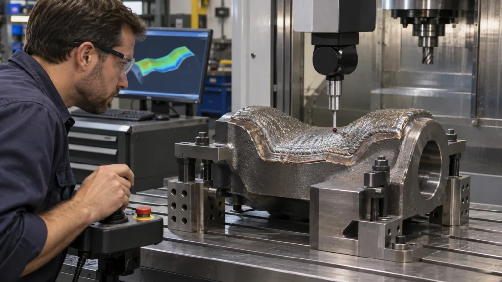
Use a staged route when needed: establish references, rough the geometry while retaining support, inspect the remaining stock, then finish the critical surfaces. A first-article scan or probing strategy may help quantify variation when the incoming geometry warrants it, but the acceptance method should be agreed rather than assumed. The site’s CNC milling page describes the general process category; confirm whether the particular Stellite form, size, and scope fit the actual quotation.
Treat edge life as a controlled variable
Stellite 6 can impose demanding cutting conditions, especially when finishing a hard layer or an irregular surface. The relevant questions are whether the tool can maintain a stable edge through the engagement, whether the setup resists vibration, and whether the operation is continuous or interrupted. Tool material and geometry should come from the tool supplier’s guidance and a controlled trial matched to the supplied material; a generic “hard alloy” speed is not a reliable production instruction.
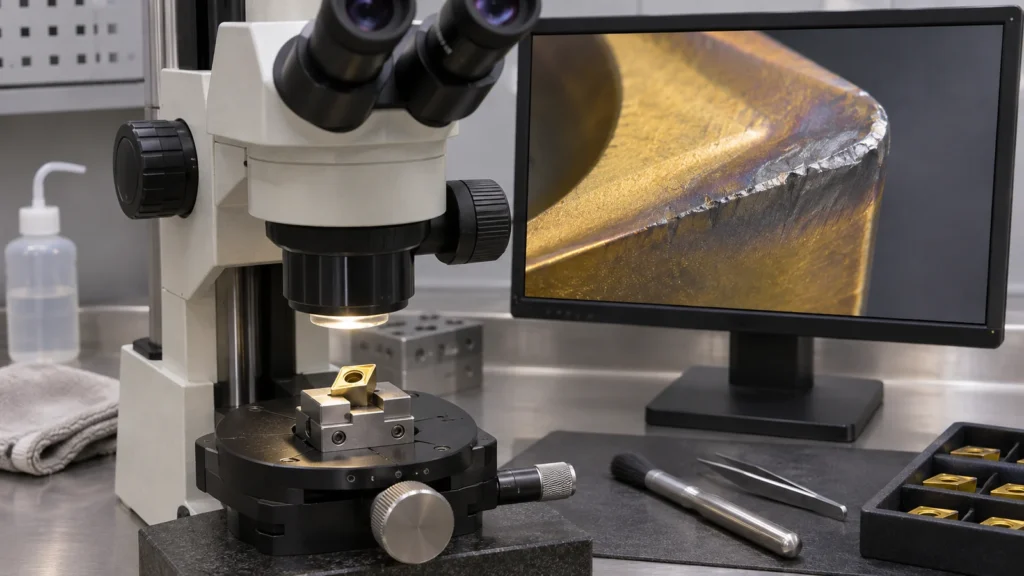
During a first-off, log tool identity, engagement, visible edge wear, cutting load trend, and the resulting finish at a defined location. Change one main variable at a time so that tool life and surface effects can be separated. If the finish degrades suddenly, check for a chipped edge, interrupted engagement, fixture movement, or inconsistent incoming stock before increasing feed or reducing speed by guesswork.
| Route condition | Risk to evaluate | Planning response |
|---|---|---|
| Hard or uneven incoming layer | Intermittent contact and localized edge damage | Map the surface and confirm cleanup allowance before final programming |
| Long overhang or thin substrate | Vibration or movement during finish cut | Support close to the feature and sequence for stiffness |
| Critical sealing or wear face | Surface damage hidden by cosmetic blending | Define the final finish and defect acceptance method |
| Material interface in the cut | Different cutting response across the path | Identify boundary location and review tool engagement in the trial |
Separate appearance from surface integrity
A uniform-looking face is not automatically a functionally acceptable surface. Identify the actual contact, sealing, or wear region and state the drawing-controlled finish or geometry there. Where surface roughness matters, specify the parameter and measurement direction; where tears, laps, exposed substrate, or edge breakout matter, define how those conditions will be inspected and accepted. Do not use a visual gloss target as a proxy for an engineering requirement.
If a grinding or polishing step follows machining, clarify who performs it and which operation establishes final dimensions. The precision grinding page describes the service category but is not a claim that every Stellite-coated component is grindable under every condition. Confirm workpiece size, material form, stock, and inspection needs before committing.
Measure the functional features after finishing
Use datums that correspond to the assembled part and measure after the final operation and release from clamping. For a coated or hardfaced part, record the location of the functional layer and verify remaining thickness if the drawing requires it. Surface-finish readings should be taken on representative functional zones, not selected only from the easiest-to-reach face.
Keep the incoming condition, process revision, material lot, and inspection record linked when the application requires traceability. If a defect is found, seek engineering disposition before blending, reworking, or removing additional material. The quality page gives general context for quality practices; the controlled drawing and purchase documents define the part-specific acceptance.
Questions to settle before quotation
- Is the stock cast, deposited, hardfaced, or another specified form, and who supplies it?
- What are the minimum and maximum cleanup allowances and remaining-layer requirements?
- Which surfaces, datums, edges, and finish values are functionally critical?
- Does the scope include only CNC machining, or also deposition, heat treatment, or grinding?
- What inspection records, first-article evidence, and traceability are required?
Answering these questions turns “finish-machine Stellite 6” into a quoteable, inspectable operation with a clear boundary around both the material and the supplier’s scope.