
For a sinker EDM cavity, electrode size is not simply the cavity size copied backward by one fixed “spark-gap” value. The finished geometry depends on the electrical working gap, the programmed electrode offset or undersize, any orbit or planetary motion, electrode wear, and the finishing sequence. These terms can be handled in the electrode model, CAM, or the machine control, but their ownership must be explicit. Start with the required cavity and its acceptance surfaces, then use the machine and electrode maker’s validated process data to derive the working electrode. A first article or test feature should confirm the chosen compensation before the same value is applied to a different material, depth, electrode area, polarity, or finish condition.
Separate cavity geometry from electrode compensation
In die-sinking EDM, controlled discharges remove material across a gap between the electrode and conductive workpiece. The cavity is therefore not a contact impression of the electrode. A side gap exists along the walls, while the bottom gap and wear behavior may be different. The finished feature also depends on how the electrode moves during roughing and finishing. This is why a nominal electrode undersize cannot be treated as a universal material allowance.
For a simple straight-wall cavity, a CAM or electrode drawing may express an undersize per side. A diameter-based value, a radial value, and a total feature difference are not interchangeable. For a non-axisymmetric contour, direction matters: corner radii, narrow slots, ribs, and local concavities respond differently to orbiting and wear. Record the convention and coordinate system beside the value.
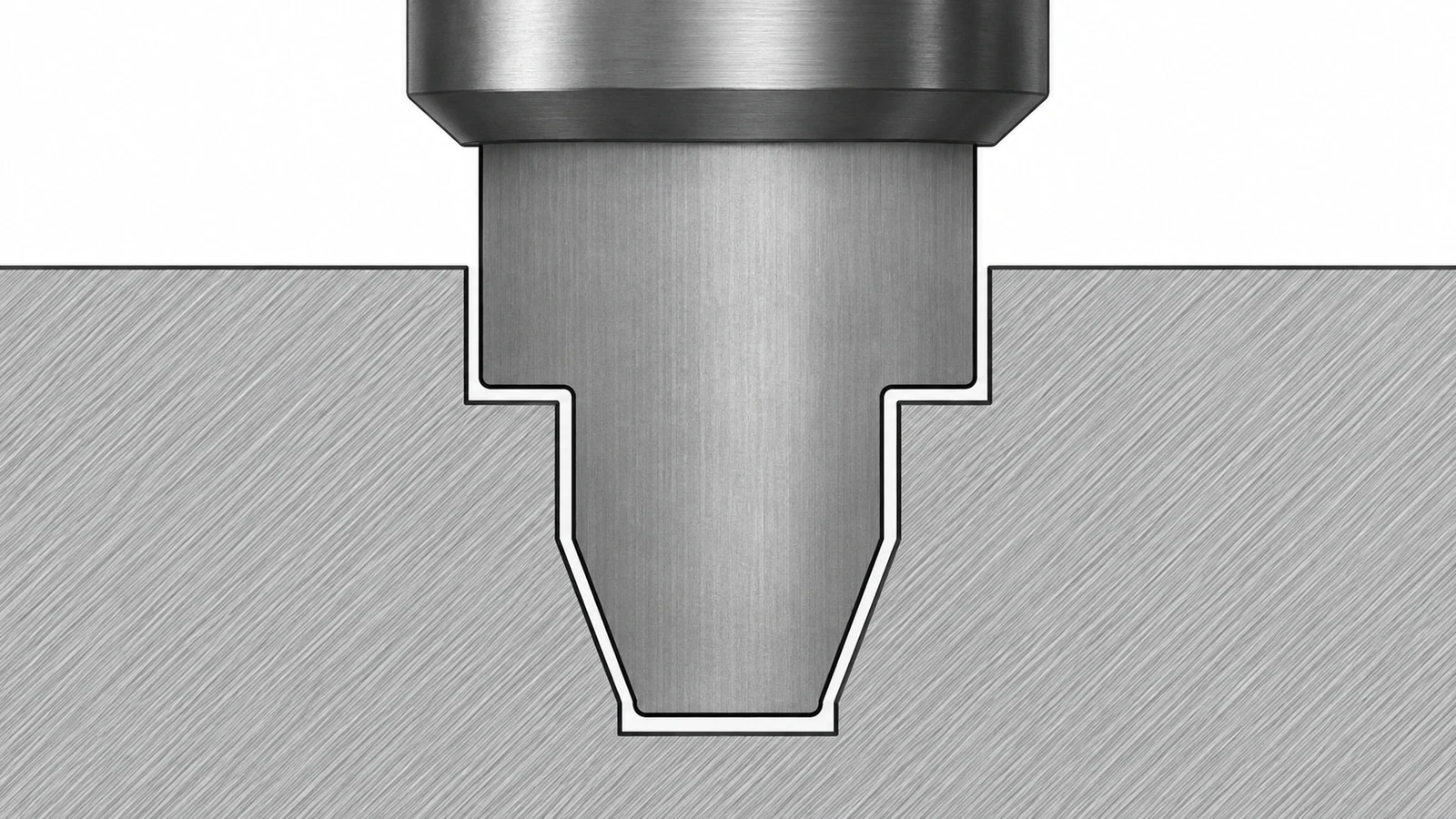
Keep the required workpiece geometry as the master definition. The electrode model should be a derived manufacturing model with its own revision and compensation record. That separation makes it possible to revise the electrode process without silently changing the part’s acceptance definition.
Choose where the offset is owned
There are three common ways to apply compensation: undersize the electrode model, apply an offset in CAM, or use a machine-control setting. Each can work if the other layers are configured not to apply the same allowance again. Double compensation can leave the cavity oversized; omitted compensation can leave it undersized. The setup sheet should say which file or control owns the value.
| Method | What must be controlled | Typical failure to prevent |
|---|---|---|
| Electrode geometry | Model revision, polarity and dimensional inspection | Undersize is repeated in CAM or at the control |
| CAM toolpath | Toolpath version, orbit and direction convention | Postprocessor or machine settings add another offset |
| Machine control | Control mode, wear table and active program values | Stored compensation differs from the released setup |
Choose a single accountable owner and preserve the other representations as nominal. The sinker EDM process page describes the process context; a part-specific electrode plan still needs its own controlled values and verification evidence.
Treat wear and flushing as geometry inputs
Electrode wear is not merely a tool-life issue. Edge and corner wear can change the cavity’s local form, and wear can differ between the electrode end and its sides. The amount depends on electrode material, workpiece material, polarity, pulse conditions, electrode shape, flushing and the intended finish. A roughing electrode may be deliberately separated from the finishing electrode so the final pass is not asked to recover a worn profile.
Deep or narrow cavities make flushing and debris removal part of the dimensional problem. Debris concentration can destabilize discharges, while restricted flow can produce local overcut, uneven wear or poor finish. Electrode jump and orbit strategies may improve access or finishing, but the resulting path changes the effective geometry. Include the intended burn sequence in the compensation review rather than sizing from the final cavity alone.
Do not transfer an offset from a different job just because the nominal electrode dimensions match. A shallow open pocket and a deep ribbed cavity can have different flushing and wear conditions even in the same alloy.
Validate the compensation on the actual burn
Use a representative test feature when the consequence of a wrong offset is significant. Match the workpiece alloy and condition, electrode material, relevant cross-section, depth, flushing arrangement and finish sequence as closely as practical. Measure the feature after the final burn, not only the electrode before use. Where the cavity contains several critical zones, inspect those zones independently instead of assuming one opening measurement represents the full depth.
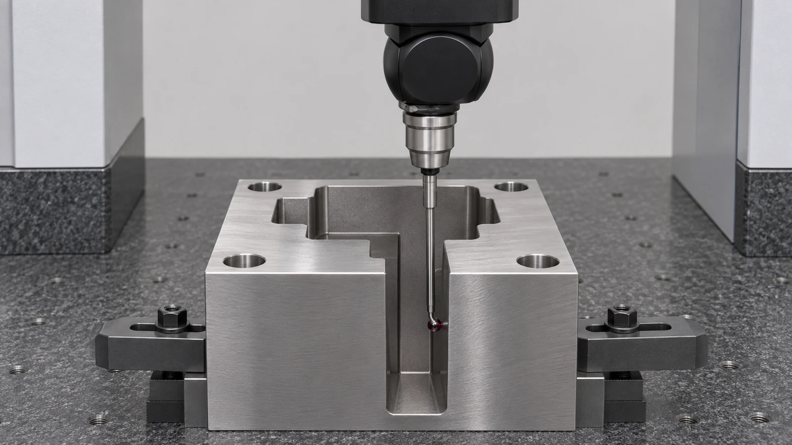
Compare the measured cavity with the master geometry and keep the result tied to the electrode and program revisions. If the feature is wrong, diagnose the chain: electrode dimensions, setup location, active offset, orbit, wear compensation, finishing stock, flushing and measurement method. Changing the nominal gap alone may conceal the source and make the next feature less predictable.
Make the drawing and handoff unambiguous
The part drawing should define the finished cavity, datums, tolerances, surface requirements and any restricted edge condition. The electrode drawing or process sheet should separately identify electrode material, polarity where controlled, compensation owner, offset convention, rough/finish sequence and inspection points. State whether any recast-layer or surface-integrity requirement applies; a dimensional offset does not define that condition.
For quoting or process review, provide the current part model, material and condition, cavity depth, critical internal radii, required texture, quantity and acceptance method. Keep the drawing as the authority for the delivered part. An electrode model is a production tool, not a substitute for a released part definition.