
Timing-pulley runout should be evaluated from the feature that locates the pulley in service, not from an arbitrary outside surface. If the bore is the functional rotational datum, mount or simulate that datum and measure the specified tooth or rim reference while rotating the part. Axial and radial readings answer different questions: one reveals face wobble or tilt, the other indicates radial variation relative to the axis. A single indicator number without a stated datum, contact location, rotation method and acceptance limit is difficult to compare between suppliers. First confirm the pulley design and drawing identify the locating bore, face and measurement feature; then select a setup that reproduces that relationship without clamping distortion.
Start with the functional datum scheme
A timing pulley can be located by a finished bore, a hub register, a clamping bushing, or another interface. The chosen datum should represent how the pulley is centered on the shaft in the assembly. If the drawing does not identify that relationship, do not assume that a convenient outside diameter is the correct substitute.
Check the assembly drawing for the shaft fit, key or clamping feature, shoulder contact and belt tracking requirements. A pulley that is dimensionally round at its outer rim can still run eccentrically if the bore or hub relationship is wrong. Conversely, a runout result taken from a rough or nonfunctional surface may exaggerate an issue that is not present at the working tooth profile.
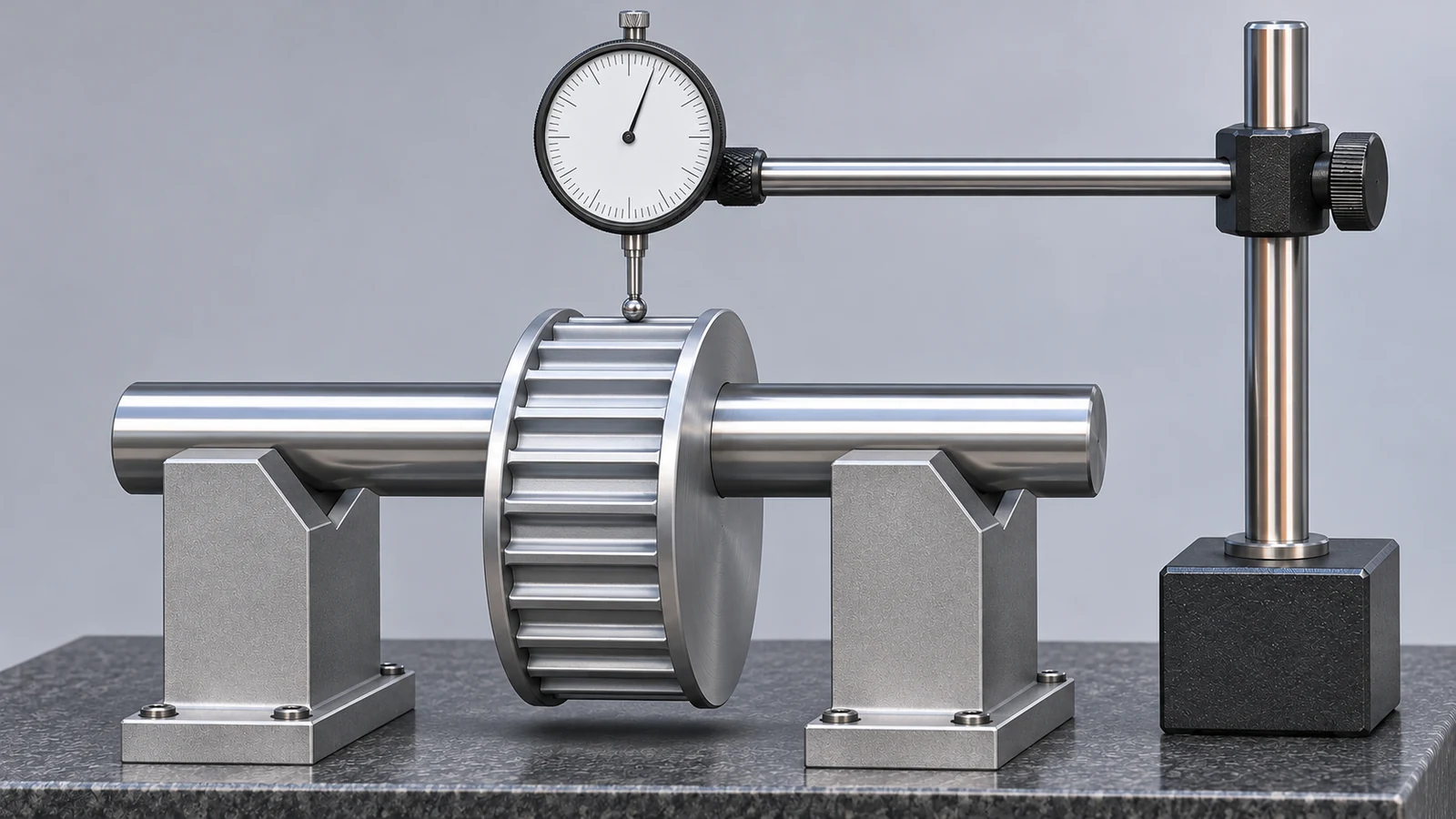
When the bore is the datum, use a suitable arbor or between-centers arrangement that locates from the bore without forcing it. The arbor fit, cleanliness, burrs and support length can all affect the reading. Document the setup so a repeat inspection uses the same locating principle.
Separate radial runout from axial wobble
Radial runout is read on a radial reference surface as the pulley turns about its locating axis. Axial runout is read on a face and is sensitive to face squareness, tilt and how the part is seated. They should not be combined into a generic runout requirement unless the drawing explicitly defines the test. A face reading may change when the datum face is dirty or the part is clamped unevenly; a radial reading may change with the chosen tooth or rim contact point.
| Check | Indicator direction | What it helps reveal |
|---|---|---|
| Radial reference runout | Radially toward the pulley axis | Centering variation of the measured rim or tooth reference |
| Face runout | Parallel to the axis | Axial wobble or angular relationship of the measured face |
| Bore size/form | Separate bore measurement | Whether the locating feature itself meets its size/form requirement |
Optibelt’s pulley guidance distinguishes radial and axial circular runout and relates tooth alignment to the bore axis, illustrating why the drawing should name the measured feature and method. Its published values apply to the scope of that manufacturer’s manual; they are not universal limits for every pulley series.
Build a repeatable measurement setup
Before measuring, remove chips and raised burrs from the bore and datum face. Seat the pulley on the specified datum and rotate it steadily through a full revolution. Use an indicator with a contact tip and force appropriate for the feature. Record the maximum and minimum reading, the total indicator variation, the location on the part and whether the measurement was taken on the teeth, an outside rim, a hub, or a face.
A simple arbor can help only when its fit and straightness are suitable for the acceptance tolerance. Excess clearance allows the pulley to shift; an interference fit or aggressive clamp can distort thin sections. If the setup error is a meaningful portion of the part tolerance, validate the fixture or use a higher-capability method before making a pass/fail decision.
For the pulley and shaft interface, the site’s CNC turning information and machined-shaft page provide related manufacturing context. They do not replace the pulley drawing’s datum and acceptance requirements.
Interpret tooth and rim readings carefully
Tooth geometry is not always a convenient continuous indicator surface. The tip profile, tooth pitch, pulley width and contact geometry determine how a probe can touch the working surface. A reading on a smooth rim may be useful for process control but should not automatically be reported as tooth runout unless the drawing or inspection plan defines the relationship.
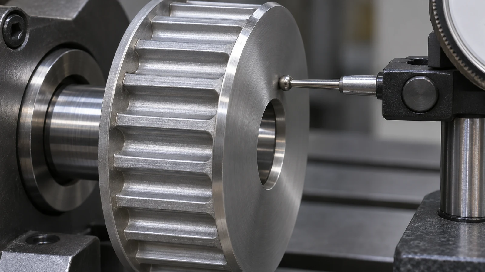
Record which tooth or span was measured and how the indicator was traversed. If belt engagement or noise is the concern, geometric runout alone may not explain the result: tooth form, pitch, parallelism, belt tension, shaft alignment and mounting conditions may also matter. Keep these as separate checks rather than broadening one runout tolerance to stand in for the entire drive system.
If a reading fails, verify the datum, arbor, debris, clamping and instrument zero before reworking the pulley. Repeat the setup, then inspect bore-to-tooth and bore-to-face relationships that the drawing actually controls. This sequence helps separate a part error from a measurement artifact.
Write an inspection callout others can reproduce
A useful callout identifies the datum feature, the surface or tooth region to measure, radial versus axial direction, the accepted limit, and any applicable product-series standard or manufacturer specification. Add the measurement support and contact approach to the inspection plan when the feature is discontinuous or difficult to access. Avoid giving a generic total indicator reading with no datum or measurement location.
For supplier review, provide the pulley drawing revision, belt profile/series, functional shaft interface, marked datum scheme and the required evidence. A manufacturer’s tolerance table should be used only within its stated product and test scope. If the pulley’s working tooth profile is critical, agree the measurement method before production so the supplier and customer do not compare different surfaces.