
Surface profile tolerance defines an allowable zone around a theoretically exact surface. To use it for acceptance, the drawing, nominal geometry, datum relationships and measurement plan must describe the same requirement. A color map or a single reported deviation is not sufficient if the supplier and customer used different CAD revisions or different alignments.
For a machined part with a curved housing, a blended passage or a shaped contact surface, the main challenge is often the handoff from design to inspection. The tolerance may be clear to the designer while leaving unanswered questions about which surface is controlled, how the part is located and what area must be measured.
Start with one controlled nominal surface
Identify the CAD model or basic geometry that establishes the true profile, and tie it to the drawing revision. A supplier should not have to decide which of several exported models is authoritative. Where a simplified manufacturing model is supplied, clarify whether it changes only presentation or the nominal geometry used for inspection.
The surface boundary matters just as much. Specify whether the control applies to a single face, a connected set of faces or another defined extent. Blends, edge transitions and adjacent surfaces should not be included or excluded merely because of how a CAD system happens to divide them into faces.
This is particularly useful when discussing five-axis milling of complex surfaces. Tool access and programming may be organized around several regions, while the functional requirement applies to one continuous surface. Manufacturing subdivisions must not quietly redefine the acceptance boundary.
Decide how the part is allowed to align
Profile can be specified with or without datum references. The complete callout determines whether the evaluation concerns form alone or also constrains the surface relative to a datum system. Referencing datums changes which adjustments are allowed when the measured part is compared with nominal geometry.
A free best fit seeks an alignment that reduces measured deviations according to its fitting rules. That may be useful for diagnosing shape, but it must not replace a required datum alignment. Otherwise, the analysis can move the part in ways that the assembly would not allow, concealing a location or orientation error.
Consider an illustrative contoured cover located in an assembly by a mounting face and two locating features. Its contour might match the nominal shape well after unrestricted fitting while sitting incorrectly relative to those locating features. A favorable shape comparison would then answer a different question from whether the assembled cover occupies the required position.
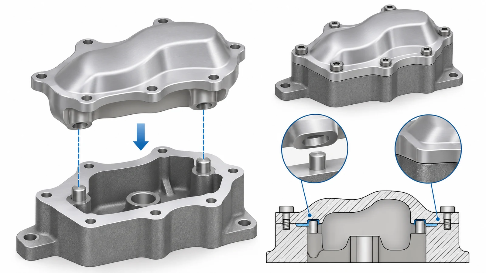
The datum setup should also account for how the part is supported without unintended deformation. If restraint is part of the specification, document it. If it is not, a fixture that pulls a flexible surface toward nominal can make the reported result misleading. The broader guide to GD&T on CNC drawings provides context for defining these feature relationships.
Read the complete zone requirement
Do not infer the distribution of a profile tolerance from its numerical value alone. Read the governing standard, modifiers, notes and any unequal or unilateral disposition that has been specified. Record how the allowed zone is positioned relative to the nominal surface before configuring the inspection software.
For a simple illustrative requirement with a total zone width of 0.20 mm explicitly distributed equally about nominal, the limits would be 0.10 mm on either side. That arithmetic is an example of a stated distribution, not a recommendation for a part tolerance or permission to assume equal distribution on every drawing.
Also keep geometric profile separate from surface roughness. A surface can have an acceptable overall contour while its texture is unsuitable, or a fine texture while its shape lies outside the allowed zone. The measurement scale, specification and evaluation method must match the characteristic being accepted.
Make measurement coverage part of the plan
An inspection samples the surface through points or measurement paths. Regions between those observations remain unmeasured. Increasing the apparent detail of a plotted color map does not create additional physical observations, so the report should distinguish measured evidence from display interpolation.
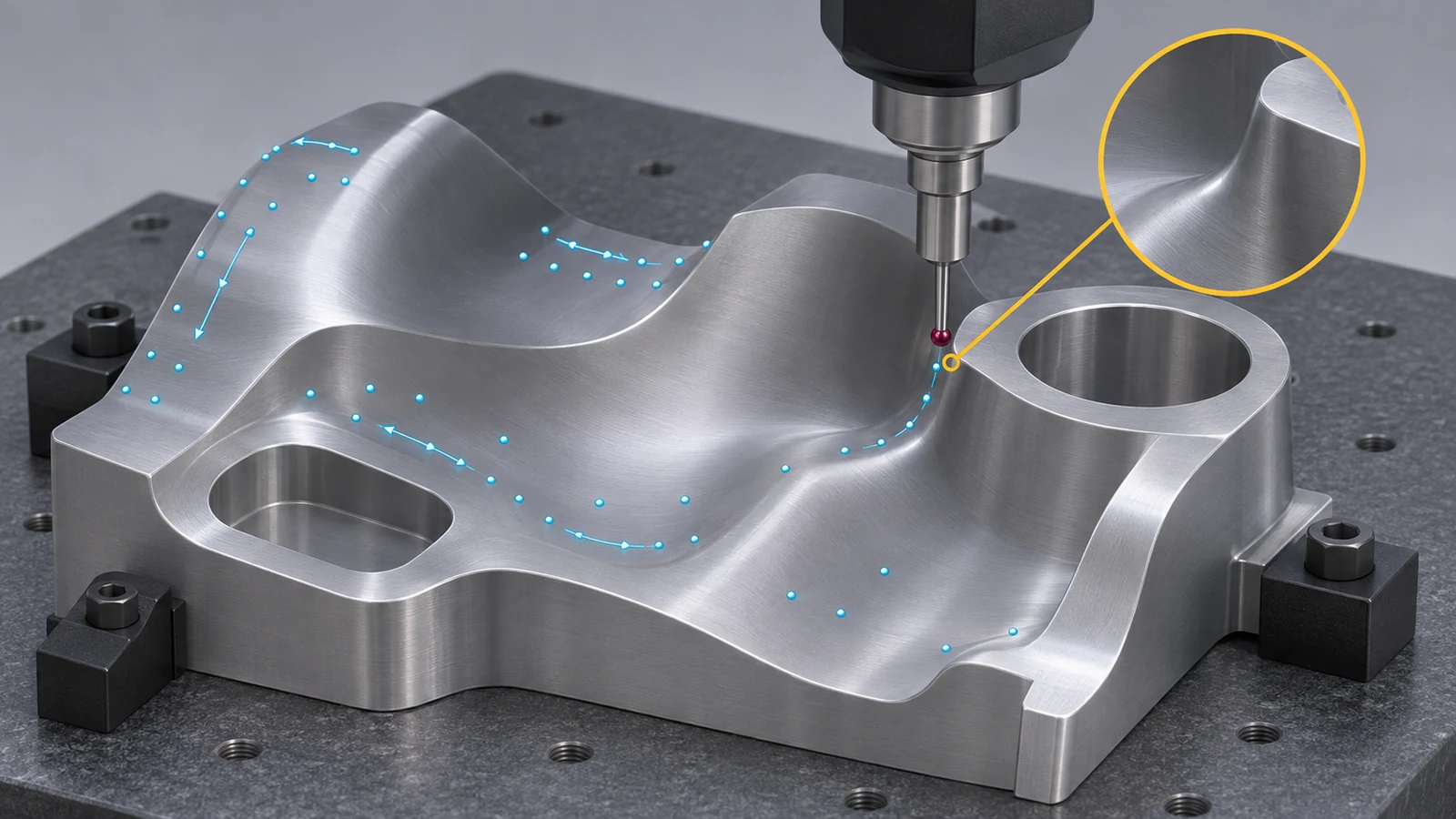
Plan coverage around the actual geometry and the deviations that matter to function. A tight blend, a transition beside a pocket or a narrow sealing region may require a different strategy from a broad accessible face. Explain how inaccessible areas are handled instead of silently omitting them from a whole-surface conclusion.
There is no single point spacing that proves every CNC profile requirement. Appropriate coverage depends on geometry, tolerance, measurement capability and the applicable inspection agreement. Supplier-specific sampling instructions can be useful references, but they should not be copied into another part’s plan without evaluating their scope.
Method selection is discussed separately in the comparison of CMM, optical and manual inspection. Once a method is chosen, the remaining task is to demonstrate that its access, alignment and coverage suit this particular surface.
Build a report that another inspector can reproduce
A reproducible report identifies the part and revision, the nominal dataset, the controlled surface extent, the datum or fitting rules, and the zone interpretation. It should describe the support condition and measurement coverage and retain enough location information to investigate an outlying result.
Show where the largest relevant deviations occur, not only their magnitude. A localized deviation near a functional transition may require a different investigation from a broad shift of the whole surface. Keep raw measurement information and evaluation settings traceable so a later reviewer can distinguish a machining change from an analysis change.
Resolve disagreement in the right order
When two profile reports disagree, compare nominal geometry and revision first, then alignment and zone interpretation, then coverage and measurement conditions. Recutting a part before resolving those differences can waste time and remove material without correcting the actual source of disagreement.
The acceptance plan is complete when another qualified inspector can follow the same controlled definition and understand what the result covers. That continuity from CAD to drawing to measurement is the practical value of a well-specified surface profile tolerance.