
A thread relief groove provides a defined space at a thread termination, often beside a shoulder. Its job is to reconcile the usable thread length, the mating part’s seating position and the clearance needed to produce the thread. It is not simply an extra recess to add whenever a tool approaches a wall. The groove also removes material, so its depth, width and transitions must be justified by the part’s function.
A common drawing problem is a threaded section that appears to run directly into a square shoulder, while the mating component is expected to seat firmly against that shoulder. The drawing may leave no clear place for incomplete threads or the tool exit. Resolving that ambiguity before machining is more reliable than discovering it when the assembly stops short.
Separate three boundaries at the thread end
First identify the end of the required full-form thread. This establishes where the mating component must still encounter the specified thread geometry. Next identify the extent of runout or incomplete thread that can be tolerated. Finally identify the surface that actually stops the assembly. These three locations may be close together, but they perform different jobs.
A dimension to the shoulder does not necessarily define the length of usable full thread. Similarly, a stated thread length should not be assumed to include or exclude the runout without checking the drawing convention. If different readers make different assumptions, the same part can appear acceptable to manufacturing and unsuitable to assembly.
A groove can provide space between the full thread and the shoulder, but its location must work with the mating part. Review the mating component’s entry chamfer, counterbore or other clearance geometry rather than considering the threaded part in isolation. The thread may be acceptable while an adjacent edge still prevents the intended seating contact.
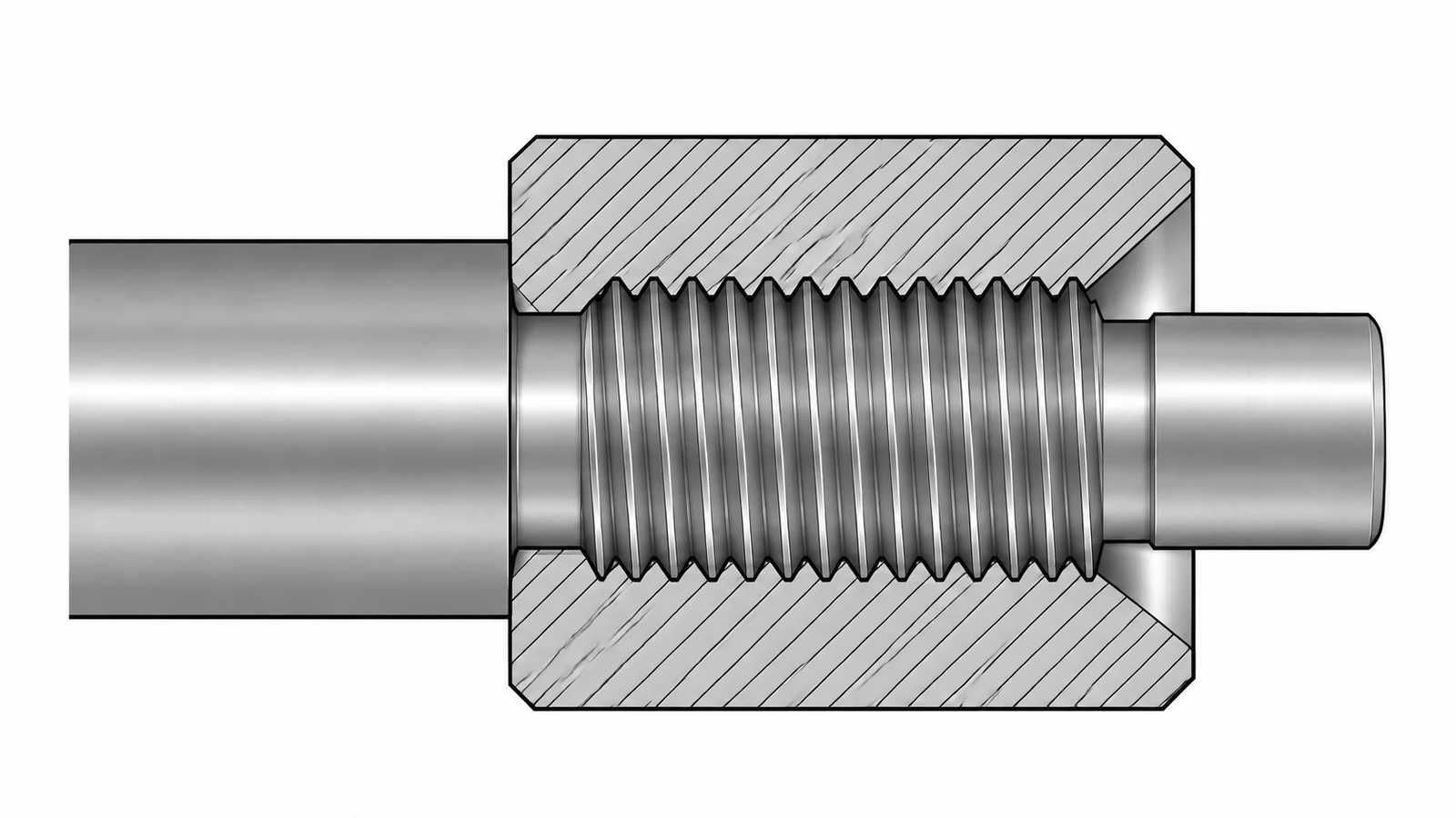
An external shoulder needs more than tool clearance
For an external threaded shaft, the relief should be considered together with the shoulder face, the mating component and the available thread engagement. A wider groove may make the thread termination easier to produce, yet move the beginning of useful engagement farther from the seat. A deeper groove may provide clearance while reducing the remaining section.
Start with a section view of the assembled pair. Show which surfaces must touch and which must remain clear. Then work backward to the required thread termination. This exposes conflicts that are difficult to see in a view of the shaft alone, such as a mating chamfer that clears the thread crest but not the shoulder transition.
The machining route is part of this discussion. The clearance required by a chosen threading operation is not necessarily identical to that required by another. Use the actual turning and threading context when reviewing the feature, while leaving the final groove dimensions under drawing control. Do not let an informal tool preference redefine a load-bearing feature.
Where a standard relief is intended, specify the applicable standard, form and edition. DIN 76-1 addresses thread runouts and undercuts for ISO metric threads, but that scope does not make one dimension set appropriate for every thread system or component. The actual dimensional requirements must come from the specified reference and design review.
Internal relief changes the access problem
An internal groove near the end of a thread must be reachable by the proposed tool and measurable by the proposed inspection method. A section that looks straightforward on a drawing can become difficult inside a small or deep bore. The issue is not only whether a cutting edge can enter; it is whether the complete feature can be produced without damaging adjacent functional surfaces.
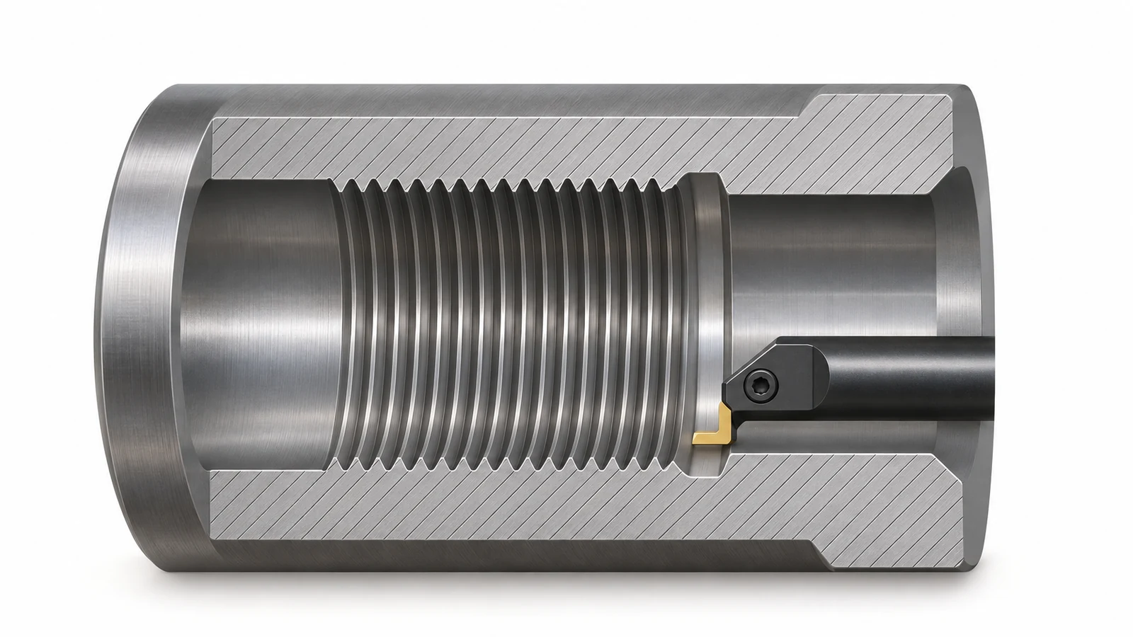
Distinguish an internal relief from drill-point space or additional hole depth. Extra depth may provide room beyond a blind thread, but it does not necessarily create the radial clearance or controlled termination required by a specific design. Conversely, an annular groove does not automatically solve every limitation associated with blind-hole threading.
The selected method also affects the treatment of chips, tool exit and the transition from complete to incomplete thread. Discuss these constraints with the supplier using the actual bore, thread and bottom geometry. The broader comparison of thread-machining methods is useful background; this local feature still needs its own definition.
When a groove creates a different weakness
A relief is not a free improvement. Removing material can change the section carrying tensile, torsional or bending loads. The groove transition may also become important to fatigue performance. Avoid choosing a sharp or deep recess solely because it makes the thread end look tidy on a model.
For a thin-walled internally threaded part, examine the wall remaining outside the relief. A radial recess that is modest on a large solid component can be significant in a small sleeve. The design review should consider the final condition, including any later finishing or material removal, rather than only the initial stock envelope.
There may be alternatives: move the shoulder, change the mating component’s clearance, revise the required engagement, or use a different manufacturing approach. These are design options to evaluate, not changes a machinist should make without approval. A custom feature discussed through custom-thread machining still needs a controlled acceptance definition.
Make the drawing and inspection agree
Before release, check that the drawing answers four practical questions:
- Where must the full-form thread end, and how much usable engagement is required?
- Which face establishes the seated position, and what clears the adjacent transition?
- Which groove dimensions and edge transitions are controlled directly or by a named standard?
- How will the thread termination and the groove be verified without relying solely on a trial assembly?
The inspection plan should preserve the distinction between a conforming thread, a conforming relief and a correctly seated assembly. A mating component that reaches the shoulder is useful functional evidence, but it does not measure every groove dimension. Equally, a measured groove does not establish the full thread length.
A well-defined relief makes the boundary between these features explicit. Its value comes from supporting the intended thread and shoulder relationship while retaining an acceptable part section, not from adding a groove by habit.