
Circularity controls the form of individual circular cross-sections. Cylindricity controls the form of an entire cylindrical surface. Choose between them by asking whether the part needs acceptable roundness at each section or a consistent cylindrical shape along the controlled length. A shaft can have round sections and still be tapered, barrel-shaped or bent enough to create a functional problem.
Two tolerance zones, different questions
For circularity, the evaluated circular section must lie between two concentric circles separated by the specified tolerance. For cylindricity, the controlled surface must lie between two coaxial cylinders separated by the specified tolerance. Both are form controls and do not require a datum reference.
| Decision | Circularity | Cylindricity |
|---|---|---|
| What is evaluated? | Circular form within individual sections | Form across the controlled cylindrical surface |
| What can a limited check miss? | Conditions at unmeasured sections | Conditions between or beyond the measured paths |
| What does the control not establish by itself? | Diameter size or alignment to another feature | Diameter size or alignment to another feature |
The difference is not that one symbol means a better-quality part. They express different requirements. Adding the broader control without a functional reason may introduce inspection and manufacturing obligations that do not improve the assembly. Choosing the narrower control when lengthwise form matters can leave the actual problem insufficiently specified.
What round sections can leave unresolved
Consider an illustrative tapered shaft. Each cross-section can be circular while its diameter changes along the length. Circularity alone does not describe that change. Whether the taper is acceptable depends on the complete drawing, including size and any other applicable controls, not on the circularity result in isolation.
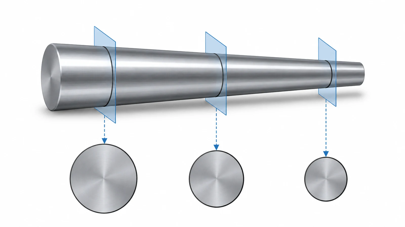
Now consider a bore that is narrower near one end or a surface with a barrel-like longitudinal shape. A check at the middle can look satisfactory while the assembled component binds elsewhere. These examples show why the location and extent of contact matter when deciding what form requirement to specify.
A long sliding contact, for instance, raises a different question from a short local seating region. Identify the surface that actually guides or supports the mating part. If separate lands perform different functions, define their requirements deliberately rather than applying a broad callout to unrelated surfaces.
Manufacturing process selection follows that functional definition. CNC turning may create the initial cylindrical feature, with another operation used where the final requirement calls for it. Neither the process name nor an attractive surface appearance demonstrates conformance to the form tolerance.
Diameter and runout are separate checks
A diameter measurement compares a size characteristic with its limits. It does not capture every possible departure around a section or along a surface. A small set of two-point measurements can therefore look consistent without fully characterizing the form. Interpretation must also respect the governing drawing standard and any size-related rules that apply.
Runout introduces a different relationship: the behavior of the surface when evaluated relative to a specified datum axis. A cylinder with acceptable form can still be positioned or oriented incorrectly relative to another feature. Conversely, a measured indicator variation can include setup or datum-related effects that should not be described simply as circularity.
This distinction matters when reviewing a supplier’s report. “Diameter checked” is not a direct answer to a cylindricity requirement. “Checked between centers” does not identify the form characteristic or acceptance rule by itself. Ask what geometry was evaluated, which reference was used and what result was calculated.
The separate comparison of hard turning and grinding addresses process selection. Here, the first task is to define the geometric result that any selected process must deliver.
Inspection must cover the shape being controlled
A measurement plan needs a reasoned distribution of sections or paths. A single circular trace may reveal the form at that location, but it cannot describe the entire length. Likewise, a small collection of points should not be presented as if every part of the surface had been observed.
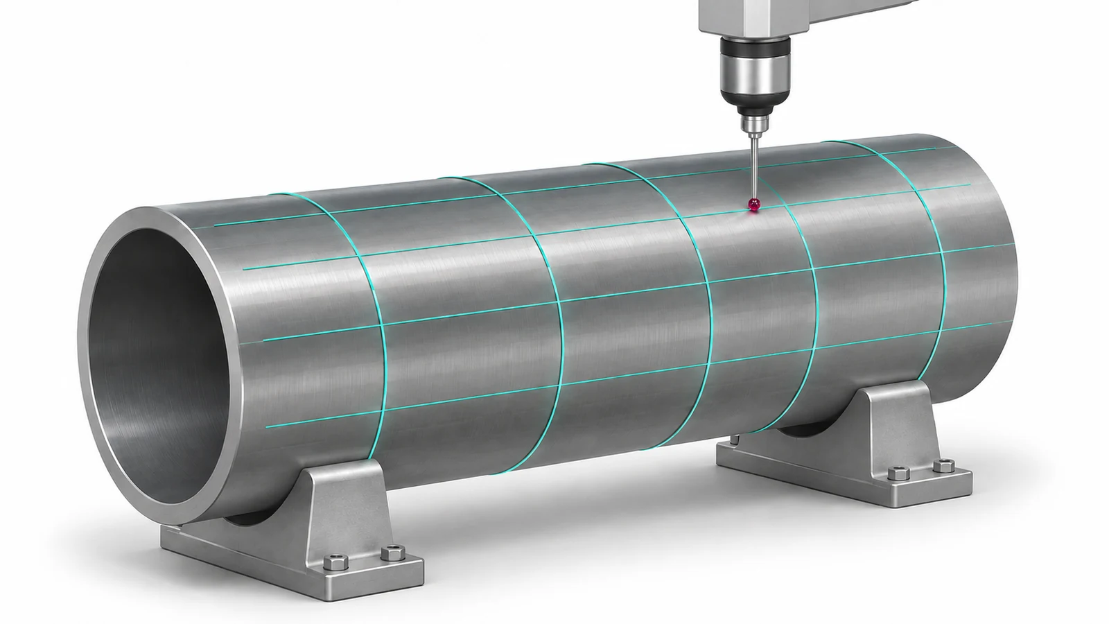
Choose coverage with the feature geometry and plausible deviations in mind. Transitions near shoulders, the ends of a bore and regions affected by support conditions may deserve attention. This does not justify inventing one universal point count. The plan should explain why its coverage is suitable for the specified feature, tolerance and measurement system.
Workholding during inspection is another part of the result. A thin or flexible part can respond to support and clamping. If the evaluation is intended for a particular restrained condition, that condition needs to be defined and reproduced. An inspection fixture should help realize the specified condition, not force the surface into a more favorable shape.
When reviewing a precision-ground surface, retain the same discipline: document the controlled length, measurement coverage and evaluation basis. Surface finish and form are related manufacturing concerns, but they are not interchangeable inspection results.
Choose from the contact, then define the check
Begin with the assembly: identify where the mating component contacts the shaft or bore and what failure would result from a departure in shape. Then determine whether circular sections alone address that failure or whether the lengthwise surface relationship must also be controlled. Review size, location and orientation separately so the form callout is not asked to do every job.
The final drawing and inspection plan should tell the same story. The symbol defines the requirement; the measurement method supplies evidence over the relevant surface. Keeping those two connected is more useful than choosing the stricter-sounding term.