
Copper tungsten machining starts with the composition and the feature that is most vulnerable to damage. A copper-rich grade and a tungsten-rich grade should not share an unquestioned cutting plan, and neither should be treated as ordinary copper or cemented carbide. For an electrode blank or a compact conductive component, the practical task is to make the required geometry without losing small edges, consuming tools unpredictably or accepting an unsuitable surface.
In this article
- Confirm what is actually inside the blank
- Choose the route around the smallest working feature
- Tool wear and edge damage need different responses
- Design access for holes, threads and narrow sections
- Separate making an electrode from designing the discharge process
- Inspect geometry and surface condition as separate requirements
- Common copper-tungsten questions
Confirm what is actually inside the blank
Copper tungsten, often written WCu or CuW, combines tungsten and copper. Supplier guidance explains that changing the copper content changes properties and machining behavior. Specify the intended grade or composition, product form and relevant acceptance requirements. “Tungsten alloy” alone is too broad: it may describe a different material family and lead to the wrong tooling assumptions.
Inspect the material documentation before planning small ribs or narrow grooves. Composition is not the only input; blank quality, dimensions and the manufacturer’s production route also matter to the job. If the application requires a particular density, conductivity or material condition, define the evidence required. A cutting trial cannot replace a missing material requirement.
A useful comparison is with the site’s copper material family. Copper tungsten belongs in that discussion for its conductive applications, but its composite character calls for a separate cutting review. Do not transfer the tool geometry, chip expectations or finishing practice of an unalloyed copper component without checking the actual grade.
Choose the route around the smallest working feature
Start with the feature whose damage would reject the part: a thin electrode rib, a narrow contact edge, a small bore exit or a thread near a wall. A broad face that machines acceptably does not demonstrate that the same route preserves these features. Qualify the exit condition and local support at the demanding detail before committing valuable blanks to the batch.
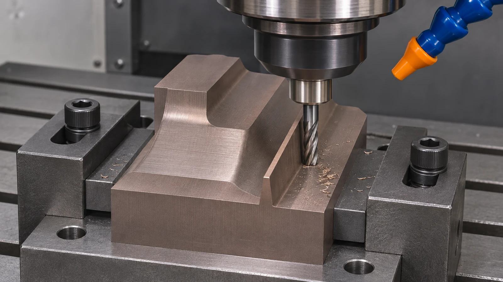 Supplier machining guides discuss conventional turning, boring, drilling and grinding of copper tungsten. They present starting guidance, not guaranteed settings. For each proposed operation, assess cutting access, holding and the condition left for the next stage. A route can combine methods, but every transfer must retain the references that establish the working geometry.
Where finishing access and geometry justify it, copper tungsten machining may include a grinding operation. Review the surface and edge requirements with that operation in mind. Grinding is not a general cure for chipped corners that are already below the required size, and a drawing should not rely on later polishing to restore missing material.
Tool wear and edge damage need different responses
A tool that gradually wears changes the effective cutting geometry. A local edge breakout in the workpiece may instead follow unsupported exit, unsuitable engagement or handling. Investigate the pattern. If several parts lose size progressively at the same feature, inspect and measure the tool. If only the final corner breaks at tool exit, review support and tool movement at that location.
Keep the process comparison controlled. Change one relevant factor, inspect the resulting edge and retain an agreed method of judging the surface. Increasing cutting speed, altering the cutter and changing coolant at the same time makes it difficult to identify what solved the problem. A successful trial should include more than an attractive photograph of the easiest face.
Fluid practice also needs operation-specific guidance. Published copper-tungsten references describe different practices for different operations. That is a reason to confirm the actual tool, grade and method, not to announce one universal dry or wet rule. Consider chip or particle removal, the surface required for delivery and any downstream joining or application restrictions when agreeing the route.
Design access for holes, threads and narrow sections
A through-hole can simplify chip removal, inspection and tapping access compared with a blind feature. Supplier guidance specifically discusses through tapping, but the drawing still needs to establish whether a through feature is acceptable to the component’s function. Do not convert a blind hole merely to make machining easier without engineering approval.
For a thread, specify the standard, engagement, lead-in and relief. Consider the wall and the material remaining around the feature. A gauge can assess the specified thread, but it does not establish that the neighboring thin section survived machining without damage. Inspect the transition and the surface where the tool enters or leaves the material.
A small radius or an intentional edge break may improve the practicality of making and handling a feature if the application permits it. Its size must come from the functional design, not a shop’s default deburring instruction. When a sharp edge is essential to an electrode or contact geometry, identify it explicitly and agree how it is inspected and protected.
Separate making an electrode from designing the discharge process
Consider a hypothetical copper-tungsten electrode with a broad mounting shank and a narrow working rib. The manufacturing drawing specifies the rib geometry and its relationship to the holder. The process planner uses the robust shank for support, protects the rib during subsequent handling and inspects the working profile from defined references. This is a plausible manufacturing review, not a validated customer application.
The electrode’s discharge allowance, wear compensation and operating settings are different decisions. They belong to the responsible EDM process design. An article about copper tungsten machining should not invent an offset to make the electrode “work,” nor should the machinist silently change a working profile to compensate for a system parameter that was never specified.
The site’s sinker EDM process page explains that separate process context. This article focuses on manufacturing the specified copper-tungsten geometry. The handoff should say whether the supplied model is the actual finished electrode or a nominal component model requiring an authorized transformation. Resolve that distinction before cutting.
Inspect geometry and surface condition as separate requirements
For a narrow rib, record thickness, profile and location using a suitable method; then inspect the edge condition. A dimension measured away from a chipped corner cannot prove that the complete working profile is present. Define where the measurement applies and what local damage is acceptable rather than requesting an unspecified “burr-free” part.
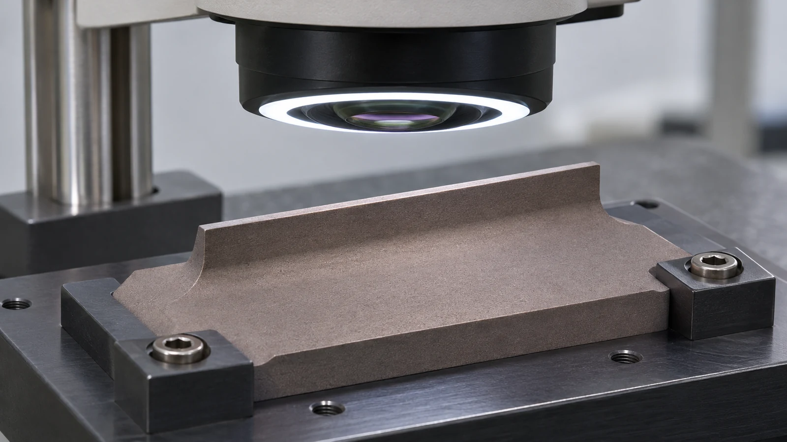 For a contact component, distinguish the locating surfaces from the area that performs the electrical or thermal duty. The final report should show the checks required by the order. Material data, dimensional inspection and application performance remain separate forms of evidence. Do not imply that a machining report proves an assembly’s electrical behavior.
Package the part so that the accepted geometry survives delivery. Support a delicate rib without loading its edge and keep loose debris away from working surfaces. The drawing review should identify which areas may be handled or gripped. A controlled machining route is incomplete if the only remaining protection instruction is “pack carefully.”
Common copper-tungsten questions
Is copper tungsten the same as tungsten carbide?
No. They are different material systems. Confirm the composition and supplier designation before choosing tooling or assuming that experience with one transfers to the other.
Does more copper mean the same cutting behavior as pure copper?
No. Copper content affects behavior, but the blank remains a specified copper-tungsten material. Use the actual grade and operation as the basis for the trial rather than replacing it with a pure-copper recipe.
Should every copper-tungsten part be ground?
No. Choose a route from feature geometry, finish, access and material guidance. Conventional cutting may suit many features; grinding must have a defined role and enough remaining material to achieve it.
Should the machinist choose an EDM spark-gap offset?
Only when that responsibility is explicitly assigned with the required process information. Otherwise manufacture the authorized electrode geometry and resolve model ownership before work begins.