
Choose 2011 for a turned component because the complete part specification suits it, not simply because the alloy cuts freely. 2011 aluminum machining can be attractive for detailed bar-work parts with repeated turning, drilling and threading. That advantage needs to survive the checks on material temper, corrosion exposure, joining and the required finish. A fast cutting cycle is of little value if the chosen stock cannot meet the drawing after downstream processing.
In this article
- Check the part’s duty before choosing free-cutting bar
- Good chip formation does not remove the need for a cutting plan
- A threaded spacer shows where the route can fail
- Decide the finish before freezing the machined dimensions
- Make the purchase specification usable at inspection
- Questions about choosing and machining 2011
A useful starting example is a threaded spacer with a locating shoulder. Its thread must assemble, its shoulder must seat, and its outside surface may need a protective or decorative treatment. Those three duties should guide material selection before the programmer chooses a feed or insert.
Check the part’s duty before choosing free-cutting bar
2011 is an aluminum-copper free-machining alloy. Published supplier data identifies additions associated with its machinability, including lead and bismuth. Specify the actual alloy, temper and product form on the purchase order. Do not substitute a nearby aluminum designation because a material chart assigns it a similar machinability rating. Such ratings compare test conditions; they do not establish the performance of the delivered component.
Start with the interfaces. A spacer inside a sheltered assembly presents a different selection problem from an exposed fitting that must be welded or match a visible anodized panel. Ask which surfaces carry load, whether a dissimilar metal contacts the part, and whether the application places restrictions on the material composition. The responsible design or compliance team should settle any composition restrictions for that product; the alloy name is not an approval statement.
For rotational geometry, 2011 aluminum machining may fit a bar-fed turning route. The relevant question is whether the bore, thread and shoulder can share reliable locating references. A hole pattern or side pocket may add milling operations, but it does not automatically invalidate the alloy. It changes the fixture, handling and inspection plan that belongs in the quote.
Good chip formation does not remove the need for a cutting plan
Free-cutting stock can make chip control less troublesome than a more ductile alternative, but chips still need somewhere to go. In a recessed bore or narrow thread relief, trapped chips can mark a finished surface or be recut. Examine the feature with the longest chip evacuation path, rather than accepting a setup because the first external diameter looks clean. The trial should include the actual bore depth, thread relief and interrupted features.
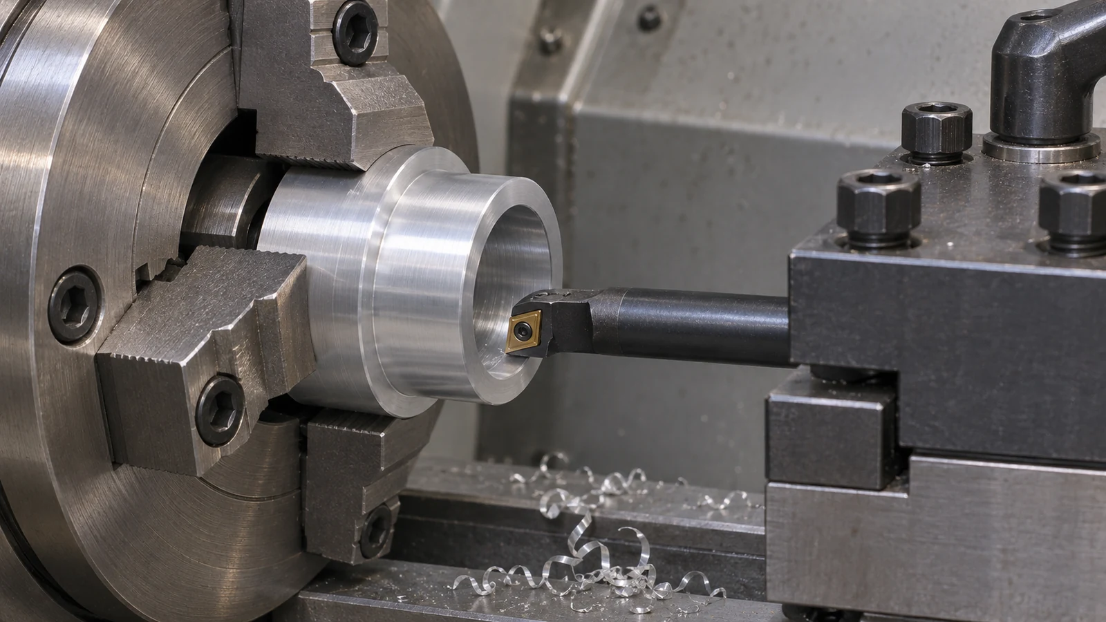 Use tooling and starting conditions appropriate to the exact stock and operation. Check the cutting edge for adhered material, wear and damage when a finish changes. Increasing spindle speed alone does not distinguish those causes. Record which feature first loses surface quality and whether the change follows cutting time, tool replacement, coolant delivery or a particular engagement. That record supports a useful correction instead of a succession of unrelated adjustments.
Small shoulders and narrow sections introduce a separate problem: support. A part can be easy to cut and still move under clamping or parting forces. Leave a stable holding region while the functional features are generated. If a second setup grips a finished diameter, define how the surface is protected and how the axial reference is recovered. For a thin spacer, inspect released geometry before treating an in-chuck measurement as acceptance.
A threaded spacer shows where the route can fail
Consider a hypothetical spacer with an external thread, central clearance bore and a shoulder that locates against a plate. The design initially specifies a tight tolerance on every diameter. Reviewing the assembly shows that the thread and shoulder control function, while the remaining outside diameter provides clearance. Relaxing that clearance dimension can reduce unnecessary finishing and inspection without weakening the functional requirements.
Plan the thread’s entry chamfer and runout together with the mating part. A thread gauge can confirm an agreed thread requirement, but it cannot demonstrate that the spacer reaches its shoulder without interference. The mating component may stop against an incomplete thread, a burr or an unsuitable relief before the shoulder seats. Inspect the transition and, where the purchase agreement calls for it, use a representative mating check alongside dimensional inspection.
2011 aluminum machining should also account for the sequence in which these interfaces are made. Finishing the bore and shoulder in a common setup may simplify their relationship; a later operation must not damage either. If parting leaves the seating face unfinished, the second operation needs a defined axial locating method. Simply measuring the overall length does not prove the seating face has the required relationship to the bore.
This example is a drawing review, not a customer case or a qualified production recipe. Its value is the separation of functional fits from clearance geometry. The same review applies to a threaded adapter or instrument spacer, but the actual loading, thread engagement and acceptance criteria remain drawing-specific.
Decide the finish before freezing the machined dimensions
The ease of machining 2011 should not be mistaken for universal suitability for welding, corrosive exposure or decorative anodizing. Published material guidance describes tradeoffs in those areas. If the assembly requires a welded joint or a closely controlled visible finish, assess that requirement with the material and finishing suppliers before purchasing a batch of bar. A process chosen for a different aluminum alloy may not transfer unchanged.
Mark the surfaces that need treatment, those that require masking and the features whose acceptance is defined after treatment. A functional thread or locating diameter may need an allowance or a protected surface, depending on the specified process. The drawing should distinguish a pre-treatment machining dimension from a final delivered dimension. Otherwise two suppliers can follow apparently correct instructions and still disagree about a rejected part.
The site’s surface finish options provide a starting point for that discussion, not evidence that every finish is suitable for this grade. For a decorative part, agree an appropriate appearance sample or acceptance method. For a functional part, prioritize fit, protection and the location of treated interfaces over an unspecified demand for a uniformly attractive surface.
Make the purchase specification usable at inspection
A useful 2011 aluminum machining package identifies the stock designation and temper, critical features, thread requirements, edge conditions and the final treatment state. Add the inspection datum and the surfaces that must be protected during handling. Refer to the relevant revision of the part drawing so that the machinist, finishing provider and inspector work from the same definition.
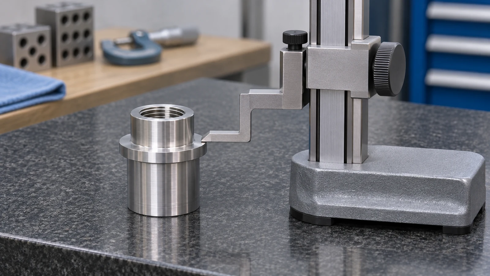 Separate surface defects by consequence. A witness mark on a clearance diameter, a raised burr on a seating face and damage on an engaged thread are different acceptance questions. Specify the functional boundaries rather than requesting an undefined “perfect finish.” Include any cleanliness or packaging requirement that prevents chips or loose debris from reaching the assembly.
Compare alternative aluminum materials when the service duty or finishing requirements outweigh the cutting benefit. The useful comparison is the completed route: stock availability, setup count, finishing, inspection and rejected-part risk. Machinability is one input to that decision, not the decision itself.
Questions about choosing and machining 2011
Is 2011 always a better choice than 6061 for turned parts?
No. Its free-machining behavior may suit detailed turned components, but the drawing also has to satisfy strength, corrosion, joining, composition and finish requirements. Compare the supplied tempers and the finished assembly duty rather than using an alloy ranking alone.
Can a clean thread finish replace a functional thread check?
No. Appearance does not establish thread size, engagement or shoulder seating. Use the specified thread acceptance method and inspect the relief and transition that can prevent assembly, with mating checks included where agreed.
Should every surface receive the same tight tolerance?
Only if function requires it. Identify the fits, seating faces and locating relationships first. Clearance geometry generally needs a different control from an interface that carries load or establishes assembly position.
When should the finishing supplier review the drawing?
Before stock purchase and final dimensional planning when a treatment affects fit or appearance. Confirm grade compatibility, masking, allowance and whether acceptance occurs before or after finishing.