
A C18150 electrode holder can have the correct outline yet perform poorly if its contact face, locating fit or delivered material condition is wrong. C18150 machining should begin with those working interfaces. Identify the chromium-zirconium copper stock and supplied condition, then connect the turning and milling route to the surfaces that conduct current, locate the assembly or transmit clamping force.
In this article
This is a component manufacturing question. It does not establish welding-system settings, qualify an electrical assembly or promise a particular conductivity from a finished part without an agreed test. The objective is a drawing that tells the machinist which features matter and tells inspection what must be accepted.
Write a material description that survives the handoff
C18150 is a copper alloy containing chromium and zirconium. Supplier references also use designations such as CuCr1Zr and CW106C, but procurement should confirm the applicable specification, product form and condition rather than relying on an informal name. A certificate for one product does not automatically establish equivalence to every other designation or the condition of a substituted blank.
The distinction from ordinary pure-copper bar matters. Strength, hardness and conductivity are related to material processing, so a purchase description that gives only “copper” leaves the route unresolved. Ask which properties are required by the application and which evidence must accompany delivery. A hardness reading, a conductivity reading and a material certificate answer different questions; none should silently stand in for the others.
If the process includes a thermal operation, its purpose and owner need to be clear. An approved material specification may define the required supplied or final condition. Do not insert an extra treatment because another copper alloy used it successfully. Discuss the proposed sequence with the material supplier and responsible engineering team, especially if a later joining operation could affect the working interfaces.
Draw the current path and the locating path separately
On an electrode holder, the external shank may locate in a clamp while an end face or internal seat provides a contact interface. Mark both paths on the drawing. A diameter that establishes alignment needs a defined fit and relationship to its seat; a contact surface needs an agreed finish and damage criterion. Tightening every dimension does not explain either task.
For a turned holder, C18150 machining can generate the locating diameter, shoulder and bore in a common setup where geometry permits. That reduces the number of times their relationship must be recovered. Any later milling operation should reference the intended datum, not a convenient unfinished side that has no controlled relationship to the working axis.
A contact face can be dimensionally flat but still contain raised burrs, embedded debris or handling damage. Those conditions may interfere with seating and create a different real contact pattern from the nominal drawing. Define which marks are unacceptable in the functional area and how it is protected through machining, cleaning and packaging. Avoid assuming a visual brightness requirement proves electrical performance.
Develop the cut around the most demanding feature
Published research on turning C18150 examines cutting conditions, tool geometry and surface response together. Its results apply to the study’s stock, tool and test conditions. They are useful evidence that the variables interact; they are not a production setting sheet for every holder. Select starting data with the actual material condition and toolmaker’s application guidance, then qualify it on the part’s demanding feature.
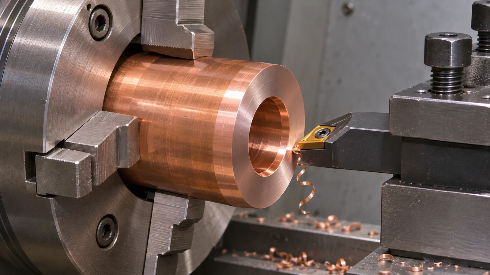 An interrupted shoulder, deep recess or small thread may reveal problems that a long external turning pass does not. Inspect chip evacuation and the cutting edge at that location. Material smearing, a damaged insert and recut chips can all leave poor-looking surfaces, but they need different corrections. Compare the surface with the tool condition before changing several parameters at once.
Holding force deserves its own review. Gripping a short finished shank can mark the very fit being accepted. A broad, suitable holding surface may protect it better, but the fixture still has to resist the cutting load. Check the part after release and after any second operation. A correct in-fixture diameter does not demonstrate that the released component or its shoulder relationship remains acceptable.
For cross-holes and threaded connections, identify the internal intersections that the final inspector cannot easily see. Plan access for deburring and cleaning before choosing the drilling order. A hole can meet its size requirement while retaining an internal burr that obstructs assembly or releases into a connected passage. The inspection method should address the actual hidden feature rather than a convenient accessible edge.
Review an electrode-holder drawing by failure consequence
In a hypothetical review, a holder has a locating shank, a threaded attachment and an annular contact seat. The first prototype assembles, but the seat shows an uneven witness pattern. Recutting the thread without investigation would miss the issue. Check whether the mating component stops at the intended seat, whether its thread runs out early, and whether a burr or a misrelated shoulder changes the contact.
Next separate geometry from material evidence. If the seat is correctly located and free of damage, an application performance concern may still require a material-condition or system investigation. The machinist’s dimensional report does not settle the welding process or the design of the current path. Assign those acceptance responsibilities before ordering another batch.
This example shows why C18150 machining benefits from a feature-based review. The drawing can specify the locating diameter and shoulder relationship, a thread and relief condition, and the surface area that must remain protected. It need not impose the same finish or tolerance on a nonfunctional outside relief. This is an illustrative engineering scenario, not a record of a customer test or delivered order.
Choose evidence for each acceptance question
The inspection package should link each requirement to a method. Dimensional checks address size and location; surface inspection addresses burrs and damage; material documentation addresses identity and the specified condition. If conductivity or hardness testing is required, name the method, location, condition and responsible party. Do not infer a finished-part guarantee from typical supplier datasheet values.
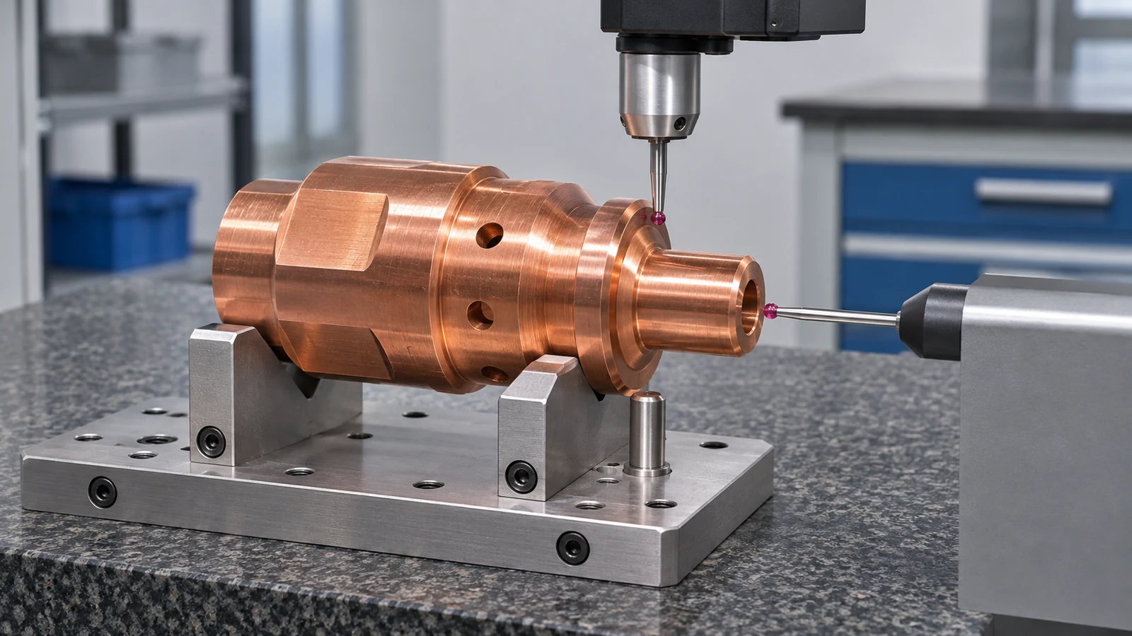 Discuss any special handling and measurement conditions with the supplier, including whether the contact face is evaluated before or after the final treatment. The quality and inspection overview can support that conversation, but the drawing and purchase agreement must define this component’s acceptance. No generic capability statement replaces an agreed inspection plan.
For quotation, provide the actual grade and condition, the mating interface information, critical surfaces and required documents. The site’s copper materials page is the material-family reference; this article’s narrower task is deciding how a C18150 part is made and accepted. Keep unrelated busbar flatness, plating thickness or welding-current design requirements in their own specifications.
C18150 component questions
Does C18150 have the same cutting behavior as pure copper?
Do not assume it does. Identify the alloy and stock condition and use suitable tooling guidance. A route developed for another copper material is a starting comparison, not evidence that the same settings will work.
Does a smooth contact face prove good electrical contact?
No. Geometry, cleanliness, mating surfaces, loading and material condition all matter to the assembly. The machining report should state what was measured; electrical or application performance requires its own agreed verification.
Must machining always happen before aging?
No universal sequence applies to every order. Follow the applicable stock and final-condition requirements and review any proposed thermal operation with the responsible supplier and engineering team.
What should accompany a quote request?
Include the drawing revision, material specification and condition, quantity, critical contact and locating surfaces, final treatment state and required inspection documents. Identify mating details when they explain a functional requirement.