
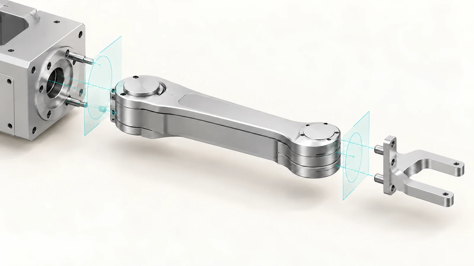
A wafer transfer arm is not just a shaped plate: it is a locating link in a robot-to-wafer handoff. The machining priority is to preserve the relationship among the robot mounting datum, arm centerline, end-effector interface, and any clearance features that control travel. A part can match its outside profile and still misplace the wafer if those interfaces are dimensioned or inspected independently.
For a machined arm, begin with the motion and contact scheme, then make the drawing express the interfaces that establish it. The exact material, surface condition, cleanliness process, and allowable deflection depend on the tool and facility; they should be specified from the equipment design rather than assumed from the word “semiconductor.”
What the arm must locate
A wafer transfer arm connects a robot or motion assembly to a wafer-contacting end effector. Its job is to carry the end effector through a defined path while maintaining the intended position and orientation at handoff. This makes the arm’s mounting and interface geometry more consequential than a cosmetic contour: a small angular or lateral error at the mounting end can appear as a larger placement error at the far end because the arm acts as a lever.
Separate three functions on the drawing. The robot-side interface establishes the arm’s position; the arm body carries load and sets reach; the end-effector interface establishes the tool or blade relationship. If one surface is expected to locate and another only to clamp, make that distinction explicit. Otherwise, a supplier may infer the datum scheme from convenient faces rather than from the machine’s actual locating method.
The interface chain matters more than the outline
Think of the assembly as a chain of references: robot face, locating feature, arm centerline, end-effector mounting face, and wafer-contact geometry. The most useful tolerances are those that control the relationships across this chain. Applying tight independent dimensions to every edge can add inspection effort without controlling the handoff any better.
| Gruppo di feature | Questione da risolvere | Drawing or inspection implication |
|---|---|---|
| Robot mounting | Which face and features establish position? | Identify the datum face and locating holes, pins, or pilot if used. |
| Arm reach | Which axis or centerline controls the end position? | Dimension the functional relationship, not only the outside length. |
| End-effector interface | How is the blade or tool repeatably seated? | Control the relevant face, hole pattern, and orientation together. |
| Clearance features | What must pass nearby during motion? | Provide envelope or keep-out information from the equipment design. |
Do not assume that a particular slot, shoulder, or hole is a locating feature because it looks convenient. Confirm the real assembly contact points. If pins locate the component and screws provide clamp force, the locating features and their relationship deserve priority over screw-hole clearance.
A route that protects the datum scheme
For a plate-like arm, a practical milling route often establishes the primary mounting face first, then creates locating features and the end-effector interface from controlled references. The outer profile can be finished after the critical faces and patterns are stable, unless the chosen workholding requires the profile earlier. This is a planning principle, not a prescribed process: part size, stock condition, geometry, and machine access can change the sequence.
Where several faces or hole patterns must remain related, ask whether one setup can machine them without losing access or support. A multi-axis route may reduce re-clamping for some shapes, but additional axes do not automatically improve accuracy; the datum transfer and inspection method still determine what can be verified. See the site’s Capacità di fresatura CNC for the process context.
Long reach and thin sections make workholding part of the dimensional strategy. Clamping can distort a slender arm, and removing material from one side may release stress or change its shape. If flatness or end-to-end alignment is functionally important, define how the part is to be supported during inspection and avoid treating a free-state measurement as equivalent to a clamped assembly condition.

Where stiffness, reach, and access compete
Longer reach can improve access but increases sensitivity to angular error and deflection. A thicker section may improve stiffness while consuming clearance or adding moving mass. Relief pockets can reduce mass, yet leave thin webs that are harder to hold without distortion. These are coupled decisions: the best geometry is the one that preserves the transfer path and interfaces within the equipment envelope, not necessarily the lightest or most aggressively pocketed arm.
Likewise, surface finish and cleanliness are separate requirements. A machined finish does not by itself establish particle-control suitability, and a cleaned part does not prove that its locating faces meet the drawing. Specify any cleaning, packaging, or handling requirements separately and confirm that the chosen process is compatible with the actual equipment and materials. Do not infer a cleanroom qualification from a supplier’s ability to machine a component.
Cosa inserire nel disegno e nella richiesta di offerta
A useful request for quotation gives the supplier enough context to protect the locating scheme without asking them to guess the machine’s function. Include:
- The 3D model plus a dimensioned drawing with revision and units.
- The mounting datum, locating features, and which surfaces clamp rather than locate.
- The end-effector interface and the relationship that must be maintained to the robot side.
- Material and temper, if selected; otherwise state that material selection is still open.
- Surface, deburr, cleaning, packaging, and traceability requirements where applicable.
- Critical-to-function dimensions and the intended inspection or assembly condition.
- Quantity, prototype/production stage, and any change-control expectations.
If the design is not frozen, send the interface envelope and motion constraints with the model. That lets the manufacturing discussion focus on access, workholding, and feature relationships rather than on a profile-only price comparison.
How to judge the finished interface
Review the arm against the same datum chain used to design it. Confirm that the robot-side locating features and end-effector interface are measured from consistent references, then check that the part seats as intended in the assembly. A report that lists individual hole sizes but omits their relationship may not answer the central question: will the mounted end effector arrive at the intended handoff position?
The right machining plan therefore starts with the transfer function, not the silhouette. Once the locating chain, motion envelope, and inspection condition are explicit, the arm’s profile and manufacturing route can be evaluated against a meaningful acceptance basis.