
A semiconductor vacuum chamber lid seals reliably only when its sealing interface, stiffness, fastener pattern, and inspection datums are treated as one system. CNC machining can produce the lid’s sealing land, groove, ports, and mounting features, but machining alone cannot guarantee vacuum performance. Seal type, mating chamber, assembly load, temperature, surface condition, and the specified leak-test method all affect the result.
For a buyer or design engineer, the first task is to identify which surfaces define the pressure boundary and which features merely provide clearance or access. That distinction keeps critical surfaces measurable without applying the tightest requirement to every face. It also makes the drawing, machining plan, and acceptance criteria agree.
Start with the Sealing Interface
A lid may use an O-ring, a formed gasket, a metal seal, or another interface defined by the chamber design. Each has different requirements for groove geometry, surface finish, compression, and handling. A drawing that says only “vacuum seal” leaves the manufacturer to guess which dimensions control assembly behavior.
Identify the actual seal type and its mating parts before assigning dimensions. The seal supplier’s design guidance and the equipment engineer’s requirements should define the groove and compression conditions; do not substitute a generic groove size from an unrelated application. If the lid seals against a chamber body, reference that mating face and the seal path explicitly.
A continuous seal path is more than a visual outline. Cross-drilled ports, intersecting channels, fastener holes, slots, and reliefs can approach or cross the sealing land. Review the complete pressure boundary in section view and make clear which openings are intentional. A small break in the path can matter more than a broad cosmetic surface that is not part of the seal.
Give the Lid a Usable Datum Scheme
Large covers often combine a broad interface face with ports, bolt patterns, pockets, and internal features. Establish a datum scheme that relates the seal land to the chamber attachment pattern and functional openings. Dimensioning each feature from a different edge can create a chain that is difficult to machine and harder to verify.
Choose references that can be located during setup and inspected after machining. If the sealing face is the primary reference, show how the bolt pattern and ports relate to it. If a pilot or register controls alignment, identify its relationship to the seal path. Use basic dimensions and geometric controls where they explain the functional relationship; do not tighten every dimension merely because the assembly operates under vacuum.
For multi-face parts, the process plan should preserve those relationships as the lid is reoriented. A suitable Processo di fresatura CNC can access pockets and interfaces, but the setup strategy depends on envelope, feature access, part stiffness, and inspection method.
Define Grooves and Ports from Their Function
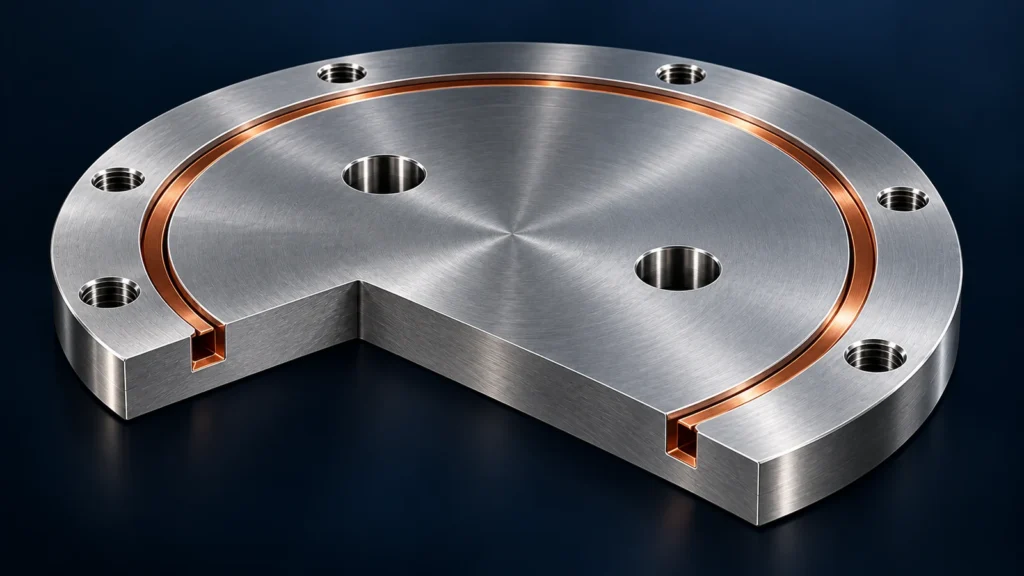
Seal grooves require clear width, depth, corner, and surface requirements that match the chosen seal and its specified compression. An undefined corner radius, burr, or tool mark can affect installation or local contact. Where the groove turns around ports or changes direction, section views help show the intended seal path and prevent ambiguous intersections.
Ports and passages should be tied to the chamber function without over-specifying features that do not control the pressure boundary. Identify which bores must connect, which holes are blind, and where threads or counterbores stop. The drawing should also state any edge-break or deburring condition where loose material could enter the chamber or damage a seal.
| Caratteristica | Drawing information to clarify | Typical review risk |
|---|---|---|
| Seal groove | Seal type, controlled width/depth, corner treatment, and datum reference | Generic dimensions may not match the selected seal or compression scheme |
| Seal land | Functional boundary, flatness or profile requirement, and finish condition | Cosmetic and sealing surfaces may be confused |
| Ports and cross-holes | Flow connection, termination, and relation to the seal path | An opening may unintentionally interrupt the pressure boundary |
| Fastener pattern | Hole positions, thread details, and relationship to the mating chamber | Uneven clamp load may distort the lid or misalign the seal |
Account for Lid Stiffness and Clamping
A broad, thin lid can change shape when it is machined, released from the fixture, or bolted to the chamber. The part may measure differently in a free state than it does under the assembled clamp condition. If the sealing result depends on a defined assembly state, the drawing or inspection plan should say whether the feature is evaluated free, supported, or under a specified load.
Fastener spacing, local wall thickness, ribs, pocket depth, and gasket reaction all influence how load reaches the seal. A machining supplier should not infer the intended bolt torque or pressure rating from the lid model. Those belong to the chamber design and assembly specification. The supplier can, however, identify a feature that is likely to move during machining or be difficult to measure repeatably.
Support strategy matters. A fixture that holds a lid flat by force may hide its relaxed shape; releasing it can reveal distortion. For thin sections, consider a sequence that leaves support in place during roughing, allows the part to stabilize when required by the material/process, then finishes the functional face and related features with controlled restraint. The exact plan must be developed from the actual geometry and material condition rather than copied as a universal recipe.
Choose a Stable Machining Sequence
Start with the stock condition, part envelope, and feature map. Roughing both sides or removing material asymmetrically can change stress balance and shape. The setup sequence should leave enough stock for a controlled finish pass on the seal land after the major pockets and ports are machined, when geometry permits.
Deep cavities, long-reach tools, and narrow walls increase deflection and access constraints. If a sealing face must remain uninterrupted, plan tool entry and exit so that marks or burrs do not cross the functional path. A separate finishing operation may be necessary, but every added setup creates another opportunity for datum-transfer error. The right decision is the one that preserves the specified geometry and can be inspected.
Material selection is also application-specific. Aluminum may be attractive for mass and machinability; stainless steel or another alloy may be chosen for chemical, thermal, or structural reasons. These materials are not interchangeable on machinability alone. The designer should specify alloy, temper or condition, and any post-machining requirements. The site’s metal materials overview is a starting point for process discussion, not a substitute for the chamber’s material specification.
Coordinate Finish, Coating, and Cleanliness
Surface finish should be specified only where it serves a defined function, such as a seal contact, mating face, bearing interface, or particle-control requirement. A general finish note can create conflict if the seal land, pocket walls, and cosmetic faces need different conditions. Identify the controlled area and state whether the requirement applies before or after any treatment.
Coatings or conversion treatments can add thickness, alter surface properties, and affect dimensions at grooves, bores, threads, or contact points. If a region must remain untreated, mark it clearly and define how the boundary is controlled. Coordinate finish requirements with the treatment provider’s process limits and the component’s assembly function. The site’s opzioni di finitura superficiale page provides process context; it does not replace a drawing callout.
Cleanliness is similarly specific. “Clean for vacuum” is not a complete acceptance criterion unless the customer defines the contamination class, cleaning process, packaging, and evidence required. Do not assume that machining, deburring, or a standard wash automatically satisfies a semiconductor tool’s cleanliness protocol. Identify the responsible party and the required condition at delivery.
Separate Part Inspection from Leak Testing

Dimensional inspection can verify the seal land, groove, ports, fastener pattern, and datum relationships. The report should identify the measurement setup and the state of the part, especially for a large or flexible lid. A coordinate-measuring machine, surface measurement, or dedicated fixture may be appropriate depending on geometry and tolerances; the method should be capable of evaluating the specified feature.
Dimensional conformance is not the same as a leak test. A lid can meet its component drawing while the assembled chamber still leaks because of the seal, mating surface, contamination, fastener load, or assembly procedure. If leak testing is part of the supplier’s scope, the RFQ must define the test boundary, method, acceptance threshold, and reporting format. Otherwise, keep component inspection and system-level qualification as separate responsibilities.
Quality records should make revision, material identity, inspection condition, and nonconformance handling traceable. The site’s informazioni sulla qualità can explain relevant process controls, while the customer drawing and purchase requirements determine what evidence is required for this lid.
What to Include in the RFQ
Send the released drawing and, when useful, a 3D model with the same revision. Include the chamber interface, seal type or specification, material and condition, quantity, finish or coating, cleanliness requirements, and the inspection evidence expected. Mark the pressure-boundary features and clarify whether ports, threads, and fasteners are included in the machining scope.
Call out the datum scheme, critical groove and land characteristics, measurement state, and any post-treatment dimensions. If the supplier must assemble or leak-test the lid, provide the mating component, sealing hardware, test procedure, acceptance threshold, and responsibility for final system approval. A component-only RFQ should not imply a chamber-level performance guarantee.
Vacuum Chamber Lid FAQs
Can CNC machining guarantee that a chamber lid will hold vacuum?
No. CNC machining can produce the specified geometry, but sealing also depends on the seal, mating chamber, assembly load, surface condition, cleanliness, and test method. Define any leak-test responsibility separately.
Should the entire lid have the same surface-finish requirement?
Usually not. Identify the seal land and other functional interfaces separately from nonfunctional faces. A blanket callout can add cost without clarifying the surfaces that control the seal.
How should the seal groove be dimensioned?
Use the selected seal’s design requirements and the chamber engineer’s assembly conditions. Specify the groove dimensions and datum relationship on the drawing rather than relying on a generic note.
Does a coating belong before or after machining?
That depends on the material, coating, fit, and seal design. State which dimensions apply after treatment and identify masked areas; confirm the sequence with the process requirements.