
Bevor jemand eine Kante schleift oder einen Offset anpasst, sollte ein aussortiertes Teil unberührt bleiben. Sein Grat, seine Bruchfläche oder seine Freizustandsform kann der beste verfügbare Beweis sein. Jedes verdächtige Stück sofort nachzuarbeiten kann die Hinweise entfernen, die nötig sind, um die nächste Aussortierung zu verhindern.
Verformung, Grate und Rissbildung bei der CNC-Bearbeitung von Kunststoffen sind unterschiedliche Fehlerkategorien. Zuerst die Beobachtung klassifizieren, dann die Stufe zurückverfolgen, in der sie aufgetreten ist, und anschließend eine plausible Ursache prüfen. Dieser materialübergreifende Leitfaden dient der Organisation dieser Untersuchung; er ersetzt keinen sortenspezifischen Zerspanungsplan. Unser Leitfadens für CNC-Bearbeitungswerkstoffe erläutert den weiteren Kontext der Materialauswahl.
Einen anhaftenden Grat von einer beschädigten Kante unterscheiden
 Verwenden Sie eine gleichmäßige Beleuchtung und eine geeignete Vergrößerung, um den Defekt zu dokumentieren. Notieren Sie seine Lage relativ zu Werkzeugeintritt, Werkzeugaustritt, Bohrungen, Ecken, Auflagern und Befestigungselementen. Fügen Sie einen Referenzmaßstab in den Prüfbericht ein, keine geschätzte Größe anhand eines Fotos.
These observations can coexist. A drilled hole may have an exit burr and a nearby crack; removing the burr does not resolve the crack. Similarly, loose chips on a surface are not automatically attached burrs. Distinguish removable contamination from damage to the component itself.
Ein Austrittsgrat erfordert eine andere Korrektur als eine verschmierte Tasche

Attached material at the tool exit
Inspect the cutting edge and the way the tool leaves the feature. An unsupported edge can bend or tear instead of separating cleanly. Check whether the final pass pushes material toward a fragile boundary, whether support can be retained longer, and whether an approved edge break would help.
A controlled secondary deburring step can be appropriate. Specify its permitted effect on nearby dimensions, sealing lands, small holes and cosmetic edges. “Burr-free” should be connected to an agreed inspection method and functional requirement, not interpreted as permission to round every edge.
Smearing inside a pocket or bore
The Mitsubishi Chemical Group machining guide identifies tool sharpness, clearance and swarf removal as important controls for plastic stock shapes. It also warns that inappropriate conditions can generate heat and damage the surface. Investigate whether the tool is cutting a chip or rubbing, and whether chips have a clear route out.
Do not apply “reduce feed” as a universal correction. A feed that becomes too light for the tool and engagement may increase rubbing. Review the cutter’s intended application and establish a controlled trial for the actual polymer, reinforcement and geometry.
A fuzzy reinforced edge
Glass- or carbon-filled grades require a different edge-quality review from unfilled polymers. Inspect tool wear and whether the observed material is an attached polymer burr, exposed reinforcement or damaged composite structure. A smoothing operation that looks better may still change the edge or leave unacceptable particles.
Chip clearing must follow machine guarding and safe operating procedures. Do not reach into an operating machine to pull stringy swarf away.
Risse über Reinigung und Montage hinweg zurückverfolgen
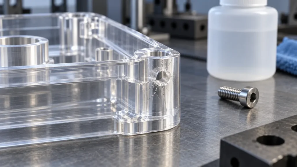 Build a short event record: machining, washing, drying, polishing or bonding, inspection, packaging and assembly. Identify the earliest stage at which the crack can be demonstrated. This is more informative than assuming that the last operation performed caused it.
For each chemical contact, record the actual product, concentration, contact time and temperature. Include cleaners, adhesives and other assembly chemicals—not just cutting fluid. Chemical compatibility can change when a polymer is stressed, so an unstressed coupon is not always a representative test.
MCG cautions that some cutting fluids can contribute to stress cracking in amorphous plastics. Use supplier guidance for the exact grade and fluid, and validate the complete cleaning sequence. A method suitable for one polymer is not automatically suitable for another.
Check mechanical contributors separately: local notch geometry, a tight interference fit, a countersunk fastener, excessive assembly force or a support that bends the part. A crack near a screw is a reason to examine the load path, not proof that the material batch is defective.
The existing PMMA melting, haze and cracking guide addresses acrylic-specific machining and optical issues. Here, the decision is broader: establish whether the problem originates in cutting, chemical exposure, assembly or their interaction before specifying rework.
Build a short event record: machining, washing, drying, polishing or bonding, inspection, packaging and assembly. Identify the earliest stage at which the crack can be demonstrated. This is more informative than assuming that the last operation performed caused it.
For each chemical contact, record the actual product, concentration, contact time and temperature. Include cleaners, adhesives and other assembly chemicals—not just cutting fluid. Chemical compatibility can change when a polymer is stressed, so an unstressed coupon is not always a representative test.
MCG cautions that some cutting fluids can contribute to stress cracking in amorphous plastics. Use supplier guidance for the exact grade and fluid, and validate the complete cleaning sequence. A method suitable for one polymer is not automatically suitable for another.
Check mechanical contributors separately: local notch geometry, a tight interference fit, a countersunk fastener, excessive assembly force or a support that bends the part. A crack near a screw is a reason to examine the load path, not proof that the material batch is defective.
The existing PMMA melting, haze and cracking guide addresses acrylic-specific machining and optical issues. Here, the decision is broader: establish whether the problem originates in cutting, chemical exposure, assembly or their interaction before specifying rework.
Eine geänderte Abmessung ist nicht immer ein Zerspanungsfehler
 Recheck the same feature with consistent datum construction and support. On compliant parts, the measuring force itself can influence the reading. If two methods disagree, establish which method represents the drawing's acceptance requirement before changing the program.
Für nylon CNC machined parts, record moisture conditioning and exposure history. Ensinger’s guidance connects water uptake and release with dimensional changes. Drying, moisture conditioning and thermal stress relief are different operations; specify the intended purpose instead of using the terms interchangeably.
Movement associated with restraint
If a part changes immediately when released, examine fixture contact and force. A compliant component can be machined while temporarily distorted. This matters particularly for soft materials such as those covered by our PTFE machining page. Changing the nominal dimension to compensate for an uncontrolled clamp condition is unlikely to produce a reliable process.
Movement after stock removal or heat exposure
Residual stress can redistribute when material is removed. Thermal exposure may also reveal movement later. Record the stock form, removal sequence and any previous treatment. Where intermediate annealing is appropriate, use a material- and thickness-specific procedure approved for the component; do not adopt one oven cycle for every plastic.
Plan sufficient material for subsequent finishing if a treatment may change size. A treatment applied after final machining can move a finished feature outside tolerance. It is not a universal rescue step.
Entscheiden, was nachgearbeitet werden kann – und es belegen
 Contain the affected parts and define the extent of the issue before releasing more work. Separate the proposal for correcting the current parts from the change intended to prevent recurrence. Both need evidence, but they answer different questions.
Agree the checks through the quality and inspection process. Retain before-and-after evidence, the approved disposition and the process revision. Acceptance of reworked parts does not by itself validate the revised process for later production.
Can a solvent wipe distinguish a scratch from a crack?
Do not use an unapproved solvent as a diagnostic shortcut. It may alter the surface or aggravate stress cracking. Use an appropriate inspection method and obtain qualified evaluation when the distinction affects acceptance.
Should every plastic part be annealed after machining?
No universal rule applies. The polymer, stock history, geometry and acceptance requirements determine whether treatment is useful and where it belongs in the process. Unplanned treatment may create a new dimensional problem.
Can a second finishing pass eliminate every burr?
No. It may reduce a particular burr, recreate one at another exit or alter a critical edge. Validate the pass on the relevant features and tool-life range, with secondary finishing where it is approved and necessary.