
Metal injection molding (MIM) is worth evaluating when a small metal component has complex geometry that repeats in a stable production program. CNC machining is often the more direct route for prototypes, changing designs, larger parts, or features that can be cut efficiently from available stock. The right comparison includes tooling, expected lifetime volume, sintering variation, secondary machining, inspection, and the cost of design changes—not just the quoted unit price.
MIM shapes a feedstock of metal powder and binder in a mold, then removes binder and sinters the part. The part changes dimension during sintering, so process control and geometry-specific validation matter. CNC starts from a solid or near-net blank and removes material; it avoids a molding die but may require more machine time and material removal for each part.
The routes solve different geometry problems
MIM is a powder-injection process for metal parts. A feedstock containing metal powder and binder fills a mold; debinding removes most of the binder, and sintering consolidates the powder into the metal component. Because the molded body shrinks during sintering, the process must be designed around controlled shrinkage, support, geometry, and material-specific behavior. The Metal Injection Molding Association describes this sequence and the characteristic shrinkage as central process considerations.
CNC machining uses cutting tools to remove material from a blank. It offers direct access to many prismatic and turned features and supports a design that is still being refined, but enclosed cavities, thin ribs, deep narrow channels, or complex undercuts can be difficult or expensive to cut. Tool access, workholding, and setup count determine what the geometry costs to manufacture.
Die Seite der Website Übersicht über Metallwerkstoffe und CNC-Fräsbearbeitungskapazität are useful for general machining context. The site also has a machined medical screw page that mentions MIM in a specific product context; it does not establish that every MIM design is a suitable machining application.
Compare the whole manufacturing route
| Entscheidungsfaktor | MIM | CNC-Bearbeitung |
|---|---|---|
| Geometrie | Can form complex small shapes if the geometry, feedstock, tooling, and sintering support are suitable | Works well when tools can reach the features and the part can be held and measured reliably |
| Upfront cost | Mold design, tooling, process development, and qualification | Programming, workholding, and first-part setup |
| Per-part cost driver | Cycle, feedstock, yield, sintering load, finishing, and inspection | Material, setup allocation, tool time, tool wear, finishing, and inspection |
| Dimensional risk | Shrinkage, distortion, support, and process variation after molding | Stock condition, clamping, cutting force, tool access, and material removal |
| Design-change impact | May require mold changes and process requalification | May require new programming, stock, setup, and inspection but not a molding die |
| Best comparison question | Can stable demand support the tooling and validate the sintered geometry? | Can the geometry be machined with acceptable material use and cycle effort? |
There is no universal volume threshold where MIM becomes cheaper. The break-even point depends on part size, complexity, alloy, tooling, annual demand, order pattern, yield, and secondary operations. Ask both suppliers to state the quantity and cost assumptions.
MIM transfers risk into tooling and sintering control
Tooling creates repeatable cavities, but it does not remove the need to control feedstock, molding, debinding, furnace conditions, part support, and inspection. Uneven sections, abrupt thickness changes, unsupported spans, and orientation during sintering can affect the result. The supplier should explain how the design is supported and how shrinkage compensation is established for the actual material and process.
Do not use a generic shrinkage percentage as a drawing allowance. Published figures vary with powder loading, binder system, alloy, geometry, and process. Require the MIM supplier to propose and validate dimensions for the specific part, identify which dimensions are as-sintered, and state which features need secondary machining or a special inspection method.
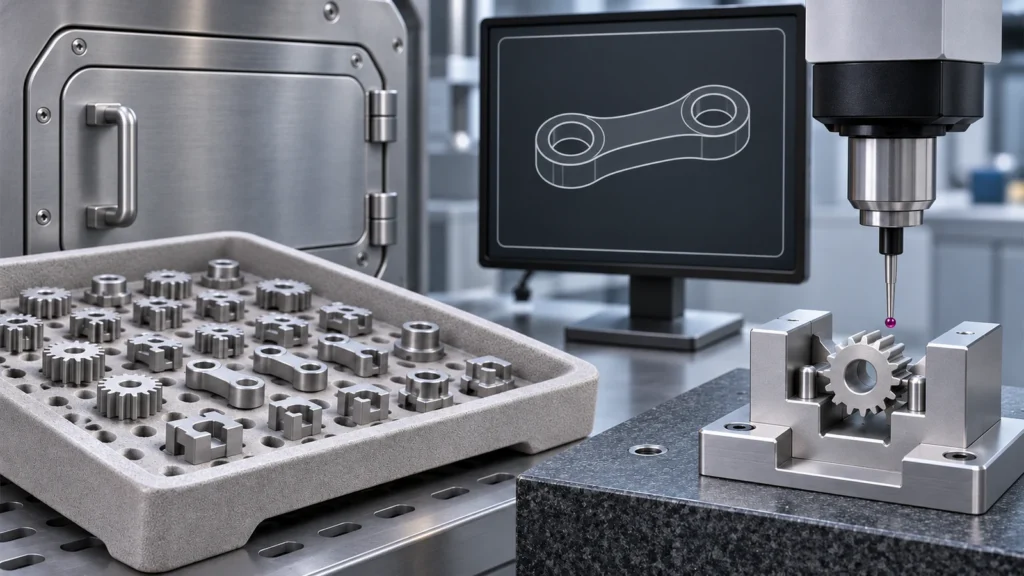
CNC keeps revisions flexible but charges for each cut
Machining can be a safer first move when the design is not frozen. If a hole moves, a boss changes, or an interface is adjusted after a fit test, a new program or setup may be simpler than changing a mold. That flexibility has a price: new material, programming, workholding, cycle time, and inspection may still be required.
CNC becomes less attractive when the part contains complex enclosed geometry, thin sections, many tiny features, or a large volume of material that must be removed from an oversized blank. Those features may demand long tools, multiple orientations, fragile workholding, or extensive deburring. A manufacturability review should test access, minimum radii, datum options, and the amount of material removed before a quote is compared.
Treat secondary machining as part of the MIM quote
MIM and CNC are not always mutually exclusive. A MIM blank can be followed by machining when selected holes, threads, faces, or fits need tighter or more predictable control than the as-sintered process can provide. The design then needs clear datums and enough stock on those features. The supplier must also explain how the part is located without distorting it and how the finished relationship is verified.
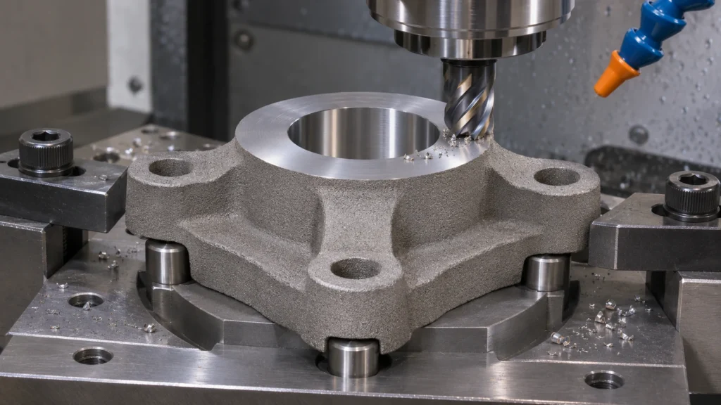
Secondary machining adds operations and handling, so include it in the MIM economics. Conversely, do not compare an as-sintered MIM quotation with a fully finished CNC part. The scope must match: same drawing revision, material requirement, surface condition, critical dimensions, inspection records, and packaging.
Make volume and acceptance assumptions visible
For both routes, send a 3D model and drawing at the same revision, material and condition, annual and release quantities, expected program life, critical features, surface requirements, and inspection documentation. Identify design elements that can change and those that cannot. Ask the MIM supplier to separate tooling from piece price and describe the qualification and sintering controls; ask the CNC supplier to show setup, material, machining, finishing, and inspection assumptions.
Use the same accepted-part definition when evaluating cost. Clarify how scrap, process yield, secondary machining, tool or mold changes, and reporting are handled. If the design is not stable, include the expected cost and lead-time effect of a revision. The best route is the one that meets the functional requirements across the real program, not the one with the lowest price at one assumed quantity.
Häufig gestellte Fragen
Is MIM only for high-volume production?
MIM generally needs tooling and process development, so the program must justify those costs over its expected life. The suitable volume depends on part complexity, material, yield, piece cost, and the alternative route.
Are MIM parts dimensionally identical after sintering?
No manufacturing process should be assumed dimensionally perfect. MIM parts shrink during sintering, and the amount and uniformity depend on material, feedstock, geometry, support, and process controls. Validate critical dimensions on the actual part.
Can a MIM part be CNC machined afterward?
Yes, selected features can be finish machined when the part can be fixtured and sufficient stock is provided. Include datum strategy, post-sinter condition, allowance, and inspection in the design and supplier review.