
A PCTFE ring can pass inspection immediately after cutting and still require a closer review of its stock and thermal history. PCTFE machining should begin with a traceable resin grade and blank, continue through a controlled removal sequence, and end with measurements in the condition specified for delivery. Low moisture absorption or a reputation for dimensional stability does not eliminate the effect of how the stock was made and subsequently processed.
The useful buyer question is therefore not simply whether PCTFE can be turned. It is which material and process history will arrive with the finished part, and what evidence shows the critical geometry remains acceptable after the agreed manufacturing sequence. This article concerns machined components, not the approval of a complete valve, cryogenic assembly or oxygen system.
Follow the material from resin to finished ring
PCTFE means polychlorotrifluoroethylene, a fluoropolymer that can be supplied as stock for machining. A resin trade name, a rod designation and a finished-part specification describe different points in the supply chain. Do not collapse them into one line reading “Kel-F equivalent” without identifying what is actually being purchased.
Daikin identifies machining as a fabrication option for its PCTFE stock. Research published through NASA on Neoflon M400H rod and valve-seat specimens also shows why the manufacturing history matters: the researchers examined changes associated with stock processing, thermal history and machining. Those results concern the tested material and specimens. They support asking for history and verification, not imposing one measured shrinkage value on every PCTFE part.
For PCTFE machining of a sealing ring, record the producer and grade, stock form, source lot, previous conditioning where specified, and the drawing revision. If the stock supplier changes, consider whether the process qualification and acceptance plan need review even when the certificate names the same polymer family.
Decide which dimensions can change the assembly
Separate the bore, outside locating diameter, axial seating face and sealing feature. Each has a different consequence if it moves. An outside diameter can change retention in a metal carrier; an axial face can change preload; a damaged sealing edge can create a local contact defect even when the overall diameter is correct.
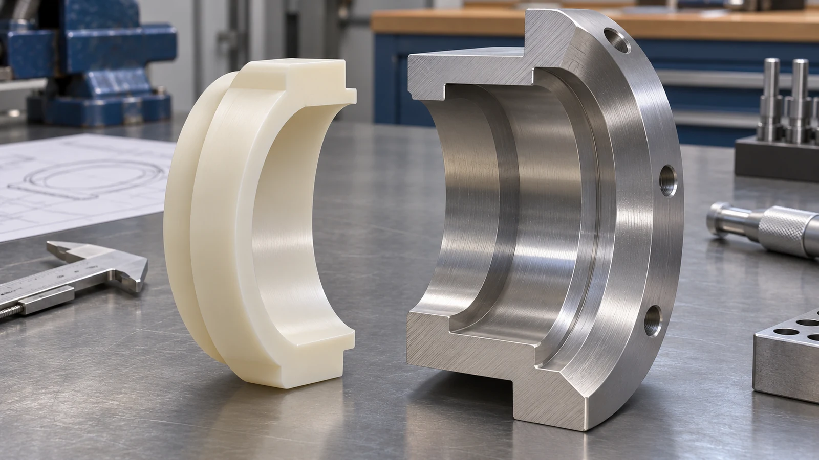 That map determines where tolerance and measurement effort belong. It may be reasonable to leave nonfunctional reliefs under the general drawing requirement while controlling the interfaces that establish compression or position. Do not add tight size limits to all surfaces as a substitute for identifying how the ring sits in its assembly.
| Feature | Assembly question | Information to define |
|---|---|---|
| Locating diameter | What holds the part without unintended distortion? | Mating geometry, fit basis and measurement state |
| Seating face | What establishes axial position or compression? | Datum, face relationship and finish requirement |
| Sealing edge | What contact must remain continuous? | Permitted edge treatment and damage criteria |
| Nonfunctional relief | Does it only provide clearance? | Envelope and burr limits without unnecessary precision |
Removal and conditioning belong in one route
Roughing changes the blank’s section and releases the finished shape from material that previously supported it. If a thermal or conditioning step is specified, the route should state whether it happens before roughing, between operations or after machining. The design authority and material supplier should resolve that sequence for the actual stock and acceptance requirement.
Do not adopt a universal annealing cycle from a different fluoropolymer or from the resin’s molding data. Heating and cooling instructions must be suitable for the grade, geometry and objective. A thermal treatment can alter dimensions; it is not automatically a corrective action that preserves every finished fit.
Preserve enough access to recover the critical datums after an intermediate step. For a ring, a separate holding surface or agreed machining allowance may be needed. Evaluate that allowance on trial geometry and material, rather than predicting all movement from a coefficient or applying the same compensation to every dimension.
The plastic materials overview is useful for family-level context. PCTFE-specific history and final-state checks must remain in the component plan, particularly when the part’s performance depends on the relationship between polymer and metal interfaces.
Inspect released geometry and protect the sealing surface
A soft or thin ring can respond to fixture force and measuring force. A measurement taken while it is pulled against a chuck or mandrel describes that restrained state. It may be useful during production, but it should not silently replace the acceptance condition for a loose component.
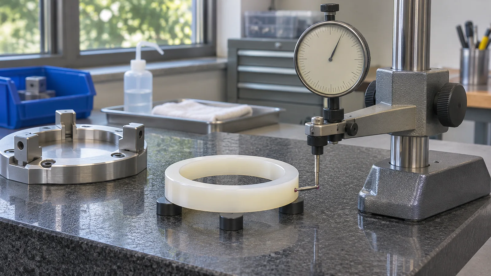 Agree the measuring method, support and environmental condition for the critical features. Where contact force could influence a reading, compare suitable methods or define a consistent low-force technique. Record the interval or process stage at which readings are taken if dimensional recovery is part of the qualification question. Avoid selecting a wait time solely because it is convenient for the machine schedule.
Surface inspection should consider scratches, torn material, attached burrs and handling damage in addition to the specified texture. Keep the working edge protected after final machining. A roughness number does not describe the entire sealing geometry, and a dimensional report does not replace any separately required leakage or application testing.
Hypothetical review: the carrier fit changes after processing
Suppose a PCTFE insert fits its inspection fixture after turning but no longer meets the intended metal-carrier relationship after a specified downstream step. The team first checks that the readings use the same datum, measuring force and temperature condition. It then compares stock identity and the actual sequence of machining and conditioning.
If the change appears only after that downstream step, adding a blanket oversize correction at the lathe may conceal the cause. A more informative trial records the relevant interfaces at defined stages and evaluates whether the route, stock condition or finishing stage needs revision. If only one thin sector changes, the review should also examine restraint and asymmetric removal rather than assuming uniform material contraction.
This is an illustrative problem-solving method, not a claim about a customer part. It explains why PCTFE machining qualification should retain the process history alongside the measurement results. The useful outcome is a repeatable route for a specified part, not a permanent correction factor for the polymer.
Details that make the request quotable
Provide the exact material requirement, the blank source if controlled, a model and dimensioned drawing, critical mating interfaces, edge and finish requirements, and the condition in which parts are accepted. Identify who owns any thermal treatment, cleaning, assembly trial or application qualification.
Specify the records needed to connect the finished component to its stock lot and route. If an alternative material source is proposed, require review of that substitution before production. PCTFE machining should not be quoted as an unrestricted promise of cryogenic performance or gas compatibility; those requirements need their own engineering basis.
PCTFE part questions
Is stock that was conditioned before machining automatically stable afterward?
Not automatically. Removal changes the section and process history. Establish whether the finished geometry requires additional verification under the applicable specification.
Can a trial ring establish a correction for every future ring?
No. Geometry, stock source, section and route can change the result. Retain the trial conditions and review changes instead of turning one observation into a family-wide allowance.
Is a smooth sealing face enough to approve the assembly?
No. Surface condition is one input. Mating geometry, material state, assembly loading and the specified functional tests must also be addressed.