
Short answer: C63000 nickel aluminum bronze machining should be planned from the certified alloy and product condition, then tuned around chip evacuation, tool engagement, and the part’s functional datums. The alloy’s strength and chip behavior make a stable, well-supported cut more useful than a generic speed chart. Confirm the exact UNS grade and supplied form; neighboring aluminum bronzes are not interchangeable merely because they look similar.
This guide focuses on wrought C63000 parts made by turning, milling, drilling, or a combined route. It does not promise corrosion performance for an unverified service environment or treat the machining operation as approval of a valve, pump, marine assembly, or pressure system.
Verify C63000 identity before quoting the route
Check the material certificate, drawing, product form, and condition before assigning a tool or inspection plan. Copper Development Association data distinguishes C63000 from related copper alloys and publishes composition and mechanical information by form and temper. The name “nickel aluminum bronze” is a family description, not enough to confirm that the supplied bar or forging matches the required grade.
Record which features are inherited from the stock and which are produced by machining. A turned shaft, a drilled passage, a seal face, and a bolt pattern impose different datum and access requirements. If a part will be coated, assembled, or exposed to a specified medium, define that downstream requirement separately from the metal-removal scope.
Plan chip flow before setting the operation order
Long or recirculating chips can scratch a finished surface, obstruct a bore, or interfere with the next tool entry. C63000 nickel aluminum bronze machining should keep chip evacuation visible in the process plan: choose an entry direction, leave a clear exit path, and avoid trapping chips between a tool and a finished face. Where the geometry produces broken or curled chips, inspect actual trial parts rather than assuming a chip form from another bronze grade.
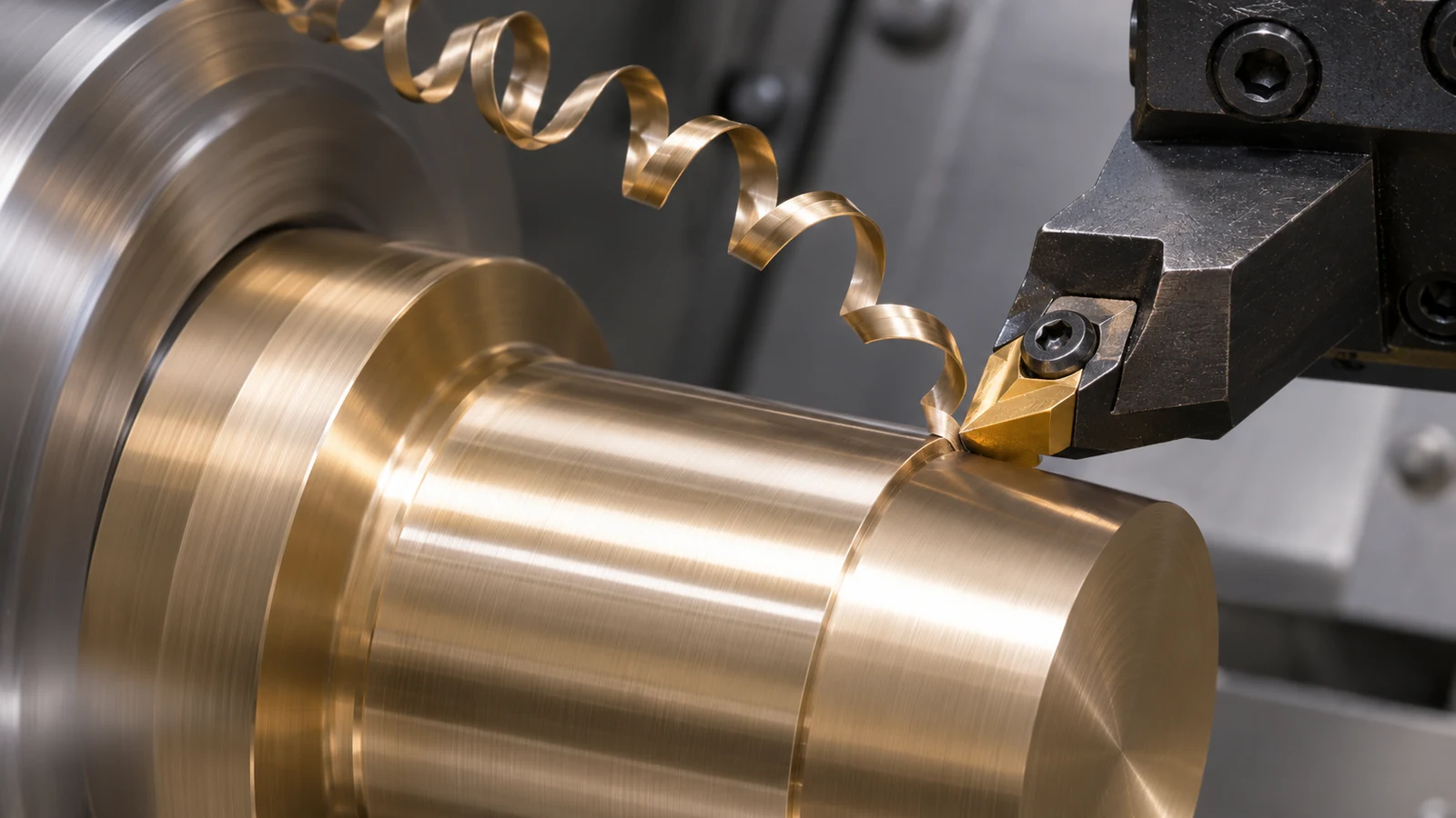 Sequence roughing and finishing so that chips from heavy cuts do not cross a sealing land or bearing surface that has already been finished. For a deep hole, account for tool reach and chip clearance. For a turned groove near a shoulder, make sure the tool can withdraw without dragging a chip over the journal.
Manage heat with steady engagement and a stable setup
Consistent tool engagement, rigid workholding, and a sharp cutting edge reduce unpredictable force and help the operator distinguish normal cutting from rubbing or chatter. Avoid unnecessary dwell and repeated shallow passes over the same track. Cutting data depends on the machine, tool, stock condition, and geometry; a published machinability index or a supplier’s generic table is not a guaranteed production setting.
When a finish changes, review insert condition, chip recutting, coolant delivery, workholding, and stock identity before changing several variables together. If the component is long or slender, support the cut near the feature where practical. If the part is asymmetric, balance material removal and recheck the datum relationship after unclamping.
Choose turning, milling, and drilling from the drawing
Turn rotational surfaces from a datum that can be recovered for cross-features. Mill flats or bolt patterns from the axis or face that controls assembly. Drill or bore passages only after confirming that tool access and chip exit are workable. A combined route can reduce re-clamping, but only if the setup preserves the functional relationship and the feature can be inspected.
For a shaft or sleeve with a sealing face, separate the turned diameter, face runout, and shoulder location in the inspection plan. For a block-like valve component, review bore-to-port position, wall thickness, and intersecting passages. The verified standard CNC turning scope and CNC milling capabilities describe relevant manufacturing routes; the drawing determines which is appropriate.
Inspect the features that control the assembly
For C63000 nickel aluminum bronze machining, do not reduce acceptance to a single diameter. Identify the surfaces that locate a mating component, seal fluid, support a bearing, or establish a mounting pattern. Define whether inspection occurs before or after any finishing treatment and which datums are used to measure position, runout, or perpendicularity.
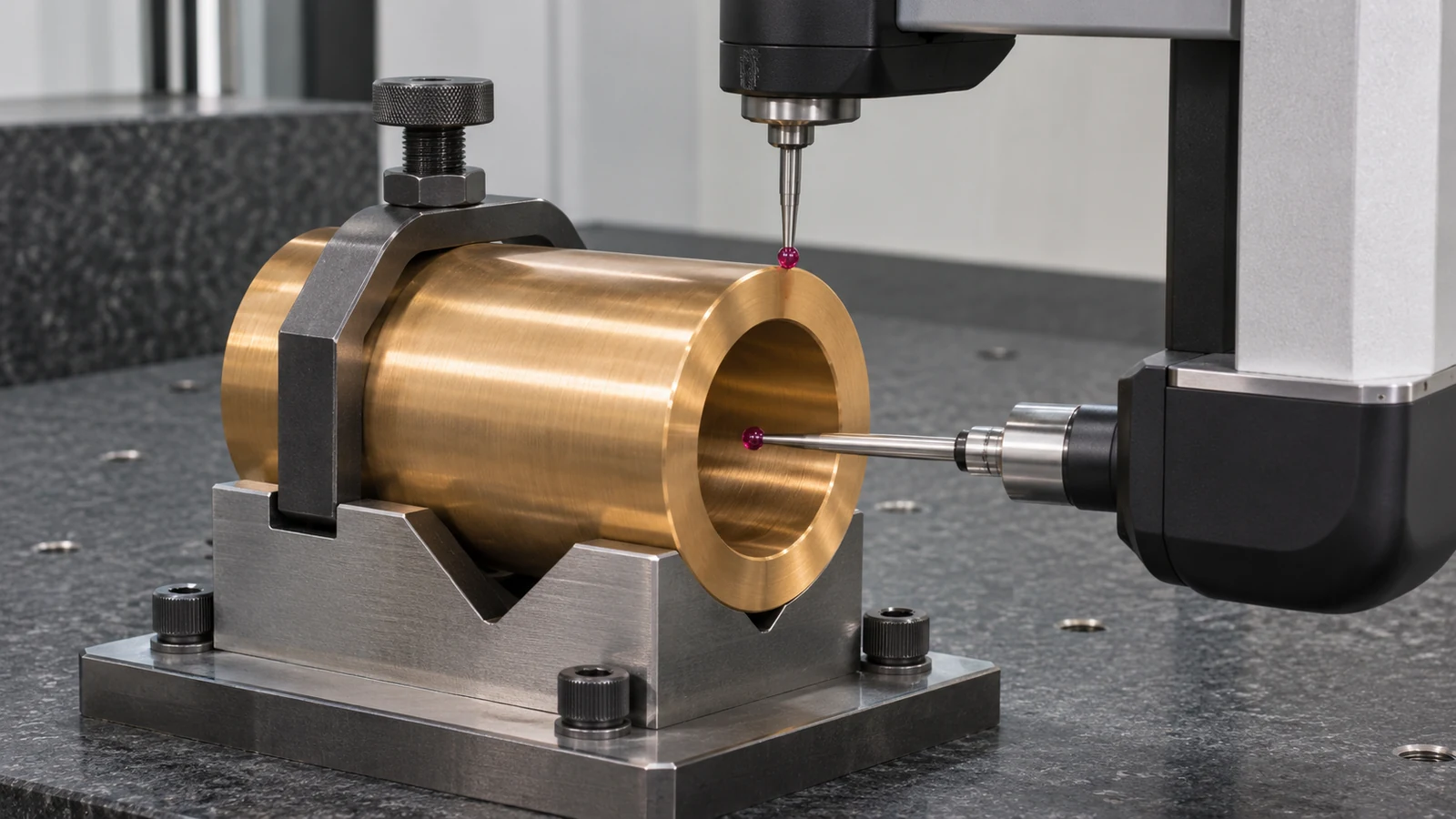 Keep alloy certification separate from dimensional inspection. A material certificate does not prove that the finished bore or face meets the drawing, and a dimensional report does not establish chemical compatibility or product-level qualification. State each required record in the purchase specification.
Illustrative review: a pump sleeve with a cross-port
Consider a hypothetical C63000 sleeve with a turned bore, an outer journal, a seal land, and a radial cross-port. The process plan turns the datum surfaces first, drills the port while preserving chip exit, then checks whether the port burr threatens the seal land. The inspection method references the bore axis and finished face rather than measuring each feature in isolation.
If the seal surface is scratched after drilling, the team reviews chip travel and operation order before simply adding a polish step. If the journal shifts after release, it reviews support and clamping. This scenario is illustrative only and does not describe a customer order or validated application.
What to send with a C63000 machining request
- UNS C63000 callout, product form, material condition, certificate, quantity, and drawing revision.
- CAD model and critical bores, seal faces, journals, holes, ports, and datum relationships.
- Chip-sensitive surfaces, deburring limits, finish requirements, and any coating or assembly handoff.
- Inspection characteristics, reports, traceability, and the condition in which the part is accepted.
C63000 nickel aluminum bronze machining questions
Is C63000 the same as every aluminum bronze?
No. Confirm the UNS designation and certified composition. Nearby grades can differ in composition, product form, and properties.
Does a machinability index provide cutting speeds?
No. A comparative index is not a direct feed-and-speed prescription. Qualify settings for the actual tool, machine, condition, and feature.
Why is chip control important for C63000?
Chips can recut, scratch finished surfaces, or obstruct a bore. Plan their path and removal before finalizing the operation sequence.
Can machining guarantee corrosion suitability?
No. Material identity and finished dimensions do not establish compatibility with a particular medium. That decision belongs to the application’s engineering specification.