
A CNC O-ring groove cannot be dimensioned reliably from the ring’s nominal diameter alone. The drawing must reflect the seal arrangement, O-ring size and compound, mating geometry, operating conditions, and assembly method. Groove depth, width, clearance, surface texture, and edge treatment work together. Machining one dimension accurately cannot compensate for an incomplete gland design.
Choose the gland arrangement first
A static face seal, a radial seal, and a seal used with motion do not share one universal groove design. Pressure direction, available space, assembly movement, and the need to retain the ring affect the selected arrangement. Use the applicable seal supplier’s design guidance for the actual application before releasing the groove dimensions.
Record the O-ring size designation and compound rather than relying on a modelled torus as the complete specification. Nominal geometry can show where the seal sits, but it does not communicate material compatibility or all dimensional tolerances. The assembly designer should own those choices and approve any proposed substitution.
This article addresses the machined gland and its manufacturing handoff. The design of a complete vacuum chamber, cold plate, or fluid manifold involves additional requirements. Keep those assembly requirements connected to the gland drawing without assuming that one groove detail qualifies the entire system.
Check depth, width, and clearance as a system
Depth influences how the seal is compressed in the assembled gland. Width contributes to the space available for the seal to deform, while the clearance between mating components affects the potential path for extrusion. Supplier handbooks treat squeeze, gland fill, and clearance together because changing one dimension can change more than one aspect of the seal.
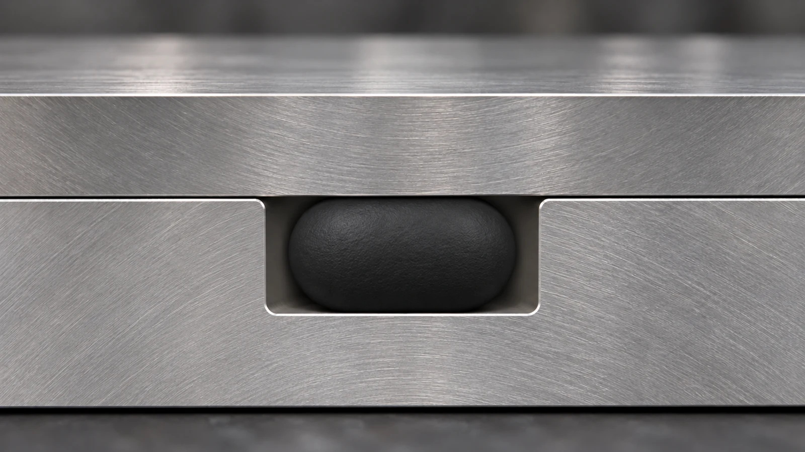
A useful design review checks tolerance extremes rather than only the nominal section. Combine the allowed O-ring size variation with the groove and mating-part limits. Consider the selected compound and operating temperature using the seal supplier’s guidance. A nominally satisfactory layout may become unsuitable at one end of the permitted tolerance range.
Do not copy a groove table from a different seal arrangement simply because its nominal ring size matches. Check the table’s assumptions, including static or dynamic service, pressure, compound, and any backup-ring provision. Record the controlling source and revision in the engineering file so later changes can be reviewed.
Translate the seal design into machinable geometry
A turned radial groove and a milled face groove require different tool access. Internal grooves can restrict the tool’s approach, visibility, and ability to clear chips. For milled grooves, corner geometry and local access should be reviewed before the designer locks the section.
The site’s CNC turning capability is relevant to rotational glands; CNC milling supports face grooves and other accessible layouts. Process selection should follow the actual geometry. A supplier should flag an inaccessible detail for review instead of quietly changing the functional section.
Specify acceptable corner radii and entry details where they affect the seal. An unrestricted ‘break all edges’ note can be ambiguous on a narrow groove or sealing land. Define the edges that need controlled treatment and distinguish them from ordinary nonfunctional edges elsewhere on the part.
Control the surface that the seal actually touches
Surface requirements should identify the groove bottom, sidewalls, and mating sealing surface as appropriate to the design. A single finish callout on the part outline may not communicate the intended contact surfaces. Texture direction and localized damage also deserve attention where they can create a path across the seal.
Deburring must remove damaging edges without changing the specified groove geometry. Inspect for remaining burrs, raised material, and scratches in critical contact regions. A visually polished surface is not automatically compliant, and an average roughness result alone does not identify every local defect.
If anodizing, plating, or another surface treatment follows machining, state whether dimensions and finish limits apply before or after that process. Confirm any masking requirement and the final measurement stage. The gland must be evaluated in the condition in which it will be assembled.
Measure the groove, then qualify the assembly
An inspection plan should connect the groove to the same datums used by its mating features. Measuring width and depth is necessary, but the location of the groove relative to a bore, bolt pattern, or sealing face can also govern assembly. Include those relationships when they affect the design.
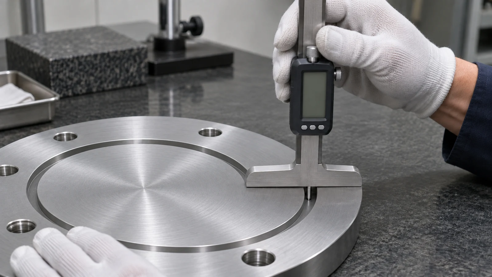
Choose a method that can reach the surfaces being accepted. Small internal grooves may require a different approach from an open face groove, so discuss measurement access before committing the geometry. The quality review should record the method and any agreed interpretation of the drawing.
Finally, separate dimensional acceptance from leak or functional testing. The assembled result also depends on the seal compound, mating component, installation, and operating conditions. Define the test medium, pressure or vacuum condition, temperature, duration, and acceptance requirement in the assembly specification. A completed groove inspection supports that test; it does not replace it.