
Haynes 230 machining should be planned around the condition of the stock, the stability of each cut, and the surface the finished component needs. A material selected for elevated-temperature service does not automatically make the machining operation tolerant of heat or rubbing. The engineering task is to turn the service requirement into a controlled manufacturing route.
Separate service temperature from cutting conditions
Haynes International identifies 230 as a nickel-chromium-tungsten-molybdenum alloy with high-temperature strength and environmental resistance. Those properties explain why a designer may consider it for a hot-service component. They do not define an acceptable cutting speed, tool life, or surface condition for that component.
The broader high-temperature material selection should establish the operating environment and required specification. The machining review then asks a different set of questions: what form arrives, which surfaces are critical, how much stock must be removed, and what processing follows the cut. Keep both sets of requirements on the route sheet.
The incoming blank changes the first operation
A bar, plate, and fabricated blank may share an alloy designation while presenting different geometry and surface conditions. Review the stock certificate, dimensions, supplied condition, and any previous operations. Determine where the first reliable locating surfaces will be established and whether the available allowance supports the final shape.
Do not transfer a machining estimate from a compact bar component directly to a thin plate feature. The distribution of removed material, support available near the cutting zone, and accessibility of the finish surfaces may be entirely different. A quotation should state the blank assumption clearly enough that a change can be recognized before cutting begins.
Where the job includes a previously processed blank, identify the boundary of the machining supplier’s responsibility. Inspection of the incoming geometry can establish whether the planned stock remains available, but it does not replace any material or process qualification required by the component specification.
Make engagement predictable before chasing removal rate
Machining guidance for Haynes 230 describes work-hardening behavior and the need for suitable cutting practice. The practical implication is to review conditions that let a tool rub instead of cutting effectively. Worn edges, unsupported reach, unsuitable engagement, and repeated passes over a problem area deserve investigation as a combination.
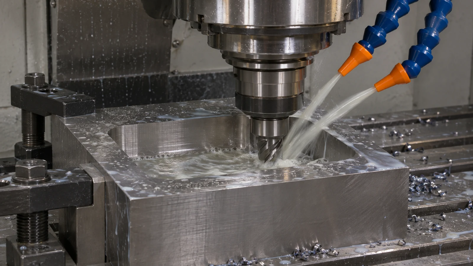
For a pocket, compare the accessible tool diameter with the pocket depth and internal geometry. For a shoulder on a turned part, consider whether the approach and exit leave the tool operating against a changing section. The milling route and turning route should be selected to keep the difficult features supported and reachable.
Use toolmaker recommendations appropriate to the actual alloy and condition as trial inputs. Then record the settings, tool geometry, coolant arrangement, and observed result. A published starting value becomes useful when its assumptions are visible; it becomes misleading when it is treated as a universal production recipe.
Plan the finish while the part still has support
Roughing and finishing should be considered together. Removing the stock that supports a wall can change the conditions for the next surface. If the last operation reaches a flexible feature with a long tool, the route may create a problem that was absent during roughing.
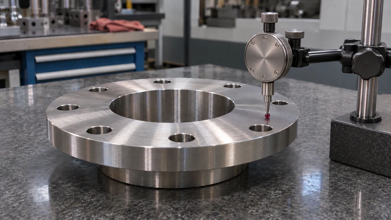
Identify the functional surfaces before setting a general finish requirement. A mounting face, a close-fitting bore, and an external clearance surface do not necessarily need identical acceptance criteria. Define the texture, geometry, and local defect limits that matter to each function rather than relying on one roughness number for the whole component.
After release from the fixture, check that the part’s geometry still satisfies the drawing. If an additional thermal or finishing operation follows, specify the final inspection stage. This prevents an acceptable intermediate result from becoming the only evidence retained for the shipped component.
Investigate variation through the process record
If dimensions or surface appearance begin to drift, first compare the affected parts with the recorded production inputs. Check material identity and condition, tool history, setup changes, and the point in the operation where the result changed. This provides a more useful starting point than assuming that the alloy is simply inconsistent.
The quality plan should identify when measurements are taken and what happens when a result approaches its acceptance boundary. First-piece approval establishes the starting condition; suitable in-process checks help reveal changes during the run.
For a repeat order, preserve the evidence behind the approved route as well as the program. The material assumption, critical setup decisions, inspection sequence, and accepted surface condition explain why the previous result was acceptable. They also make it easier to judge whether a changed drawing needs a new trial.