
A PVDF passage is not finished merely because a drill has connected two ports. PVDF machining needs an agreed condition for the intersection, an accessible method of removing attached material, and a way to inspect the result. Start by marking which edges contact a seal or fluid stream and which may be relieved. Then decide how the component will be cleaned and accepted. Neither a clean-looking outside surface nor the polymer name proves the condition inside a passage.
PVDF, or polyvinylidene fluoride, is used in engineering components where its material properties suit the duty. Ensinger describes milling and turning of PVDF stock shapes and other blanks. The discussion here concerns how to specify a machined part; it does not establish the chemical compatibility, purity rating or service life of an unspecified fluid system.
Draw a passage map before selecting operations
Take a small distribution block with an axial bore, two cross-drilled ports and a mounting face. Mark the tool entry, the intersection and the exit for each passage. A drill that reaches the intersection does not necessarily leave room for a deburring tool or a camera. Design those access requirements together while the geometry can still change.
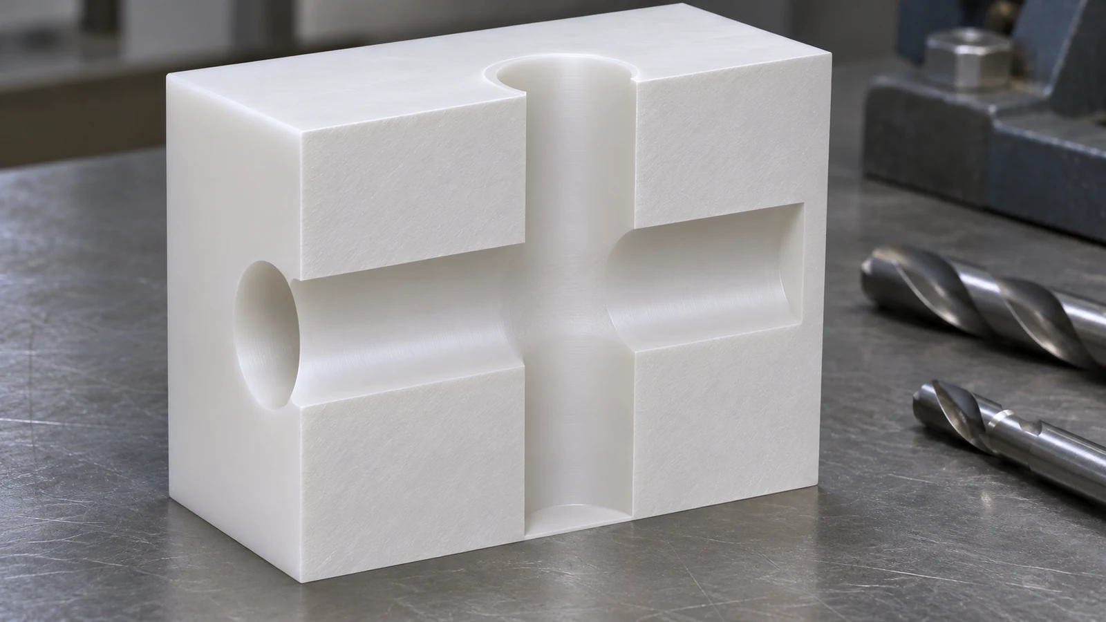 Ask whether a through-passage, removable closure or revised port orientation could make finishing and inspection possible without altering the intended function. Any closure also creates a sealing and cleanliness question. Do not introduce a plug solely to simplify cutting without reviewing what it adds to the assembled system.
Separate passage geometry from mounting geometry. The ports may need a relationship to a seal face while the outside mounting holes only need enough accuracy for assembly. Defining those tasks independently prevents the entire block from inheriting the tightest requirement on one interface.
Identify the edge that is actually being accepted
An attached burr, a smeared lip, a torn edge and a deliberate chamfer are different conditions. A drawing that says only “deburr” can leave one supplier breaking every edge while another removes loose material but preserves sharp functional transitions. State the acceptable edge treatment at the locations where it changes sealing, insertion or flow.
| Location | Potential problem | Useful drawing or process instruction |
|---|---|---|
| Cross-bore intersection | Attached material remains beyond easy sight | Define removal and inspection access |
| Seal-entry edge | A sharp or damaged lip harms insertion | Define the permitted lead-in and surface condition |
| Thread entrance | Loose chips or a distorted first thread | Inspect the entrance after cutting and cleaning |
| Mounting perimeter | Unnecessary cosmetic rework | Separate handling edges from functional interfaces |
For PVDF machining, the operation sequence should leave the most sensitive interfaces protected from later chip travel and tool contact. If a sealing land is finished first and subsequently crossed by chips from another operation, the final inspection must still assess its actual delivered surface.
Cut cleanly without using the fixture to hide movement
Heat and restraint influence polymer geometry during machining. A tool that rubs instead of cutting can change the surface, while a fixture can hold the component in a shape that it will not retain after release. Use tool condition, support and chip evacuation as connected process variables rather than treating a smaller feed or a tighter clamp as an automatic improvement.
On a block with a deep passage, accumulated chips can increase rubbing and obscure whether the drill is still cutting effectively. On a thin mounting ear, the same force may produce local deflection. Inspect the relevant feature after release before concluding that the machine’s in-cycle position demonstrates the finished geometry.
The trial should use the actual grade and stock form. Record any coolant or cleaning restrictions before selecting a cutting fluid. A material compatibility concern should be resolved with the stock supplier and application owner; a generic claim of chemical resistance is not approval of every fluid used during manufacturing.
Deburring, cleaning and proof are separate deliverables
Deburring removes or modifies unwanted attached material. Cleaning removes specified contamination. Inspection establishes whether the required condition has been achieved. Cleaning alone cannot be assumed to remove every firmly attached lip, and a burr-free edge can still carry unwanted residue.
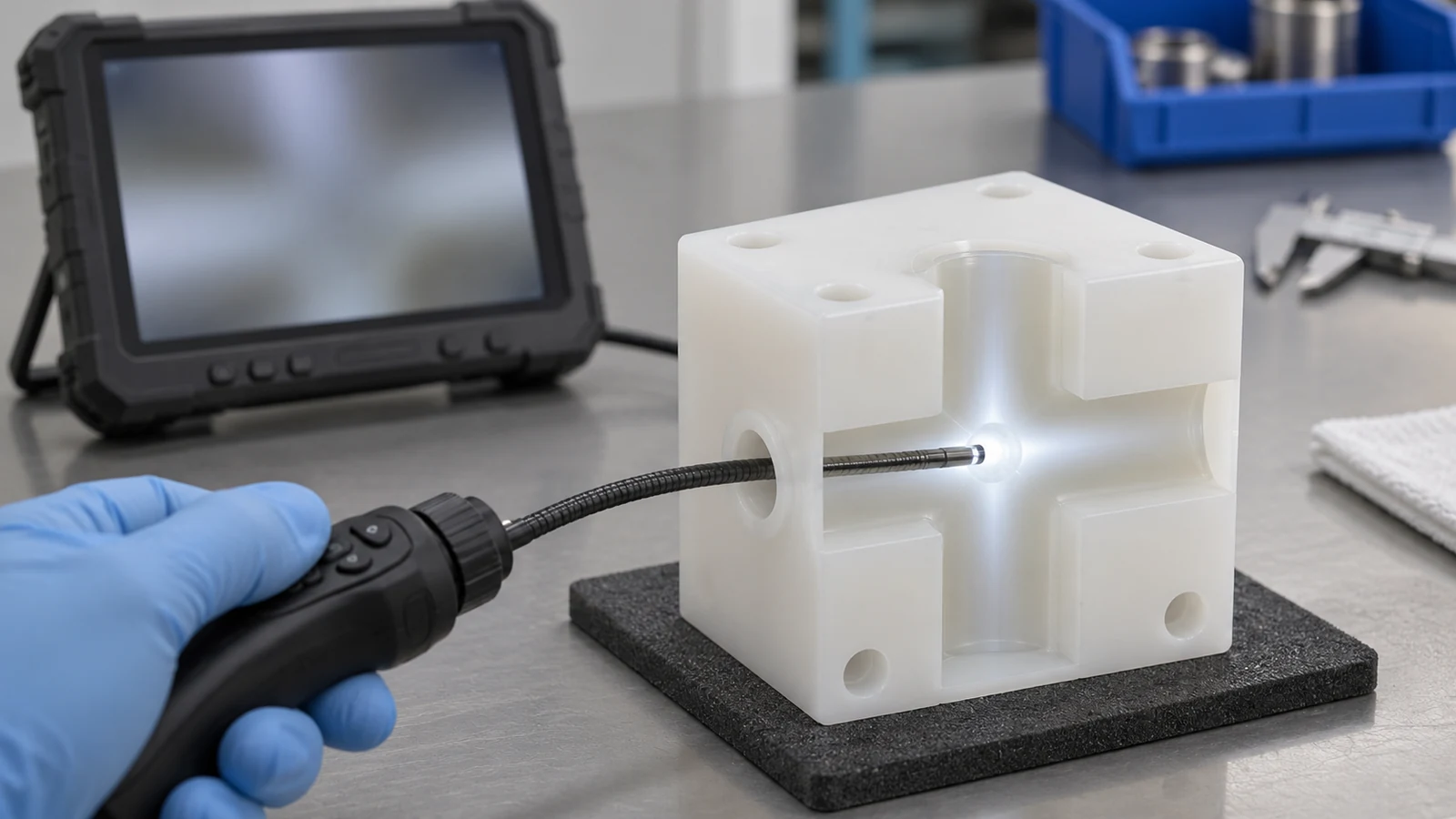 Agree what must be inspected, how it can be reached and what the inspection record will show. A borescope may reveal a visible lip but cannot automatically quantify an edge radius. A flushing result may support a defined residue requirement but does not prove the geometry of an inaccessible intersection. Match each method to the question it can answer.
For sensitive passages, identify the allowed manufacturing aids, wash medium where controlled, drying condition, handling and protective packaging. If the buyer needs a particle limit or another cleanliness test, name the method and acceptance basis separately. This component-level agreement is more precise than an unsupported label such as “ultra-clean PVDF.”
Release a drawing that the inspector can use
Include the exact PVDF requirement, a model and drawing, datum relationships, port and thread specifications, controlled edge details and any restricted residues. Show the assembled seals or mating geometry where they explain the functional surfaces. Keep general tolerances on noncritical areas unless a particular function justifies a tighter limit.
The plastic material reference helps organize material choices, but the released drawing must identify the actual grade and finished-part requirements. A quotation should explain any inspection access that cannot be achieved and any cleaning requirement that needs a separate qualified process. PVDF machining acceptance is strongest when the geometry, surface and residue requirements are individually verifiable.
Practical PVDF questions
Should every internal edge have the same chamfer?
No. Seal entries, thread starts and flow intersections serve different functions. Specify the intended edge where it affects performance and review accessibility.
Can a clear flushing liquid prove a cross-hole is burr-free?
No. An attached lip can remain while the liquid appears clear. Use an inspection method that addresses the intersection itself.
Is PVDF coating the same scope as machining PVDF stock?
No. Coating a metal component and removing material from a polymer blank involve different substrates, processes and acceptance criteria.
What should change when the stock form changes?
Review holding, material removal, inspection and any approved qualification. A different blank may save material without reproducing every behavior observed in the original trial.