
A small chip at a PBI bore entrance can matter more than a smooth finish on the rest of the part. PBI machining should protect the edges and sections most likely to be damaged during holding, tool entry or breakthrough, while preserving the stock condition used to qualify the process. Start with the exact material and feature duty; then choose support, cutting order and inspection. High thermal capability does not make a thin edge immune to mechanical damage.
PBI stands for polybenzimidazole. PBI Performance Products distinguishes its U-series stock shapes from T-series compounds blended with other polymers. That distinction belongs in the drawing and material record. A manufacturing route qualified for one stock grade should not be transferred to a blend just because the names both contain PBI.
First identify the material that will become the part
Record the grade, producer, stock form and condition, plus any required storage or conditioning instructions. The material certificate and the blank identity should remain connected after the stock is divided. For a small batch of expensive components, mixing blanks or losing that connection can make a dimensional investigation inconclusive.
Supplier information for Celazole U-series discusses moisture and the condition of stock shapes. Resolve the state in which machining and acceptance will occur with the material source. Avoid assuming that all delivered blanks, opened packages and partially machined parts have the same history. Where moisture protection is specified, include the transitions between storage, cutting, outside processing and final packaging.
For PBI machining, this material definition is more useful than a broad “high-temperature plastic” description. The buyer must still establish whether the selected grade suits the application; the machining supplier’s task is to make and verify the agreed component.
Mark fragile transitions before planning the first setup
Review thin rims, abrupt section changes, narrow webs, small mounting ears and the exits of drilled or bored features. A notch-sensitive material can concentrate stress at a sharp transition. The engineering question is whether the corner or edge is required by function, and what radius or edge treatment can be permitted without compromising the mating part.
A cosmetic edge break is not a replacement for a functional radius. Likewise, a large chamfer that makes cutting easier may remove contact area or alter the position of a seated component. Put those decisions on the drawing. The machinist should not have to choose between an undocumented design change and an unnecessarily fragile feature.
Consider a stepped insulating spacer with an accurately located bore and thin end flange. The flange may need temporary support while the bore is finished, but that support must not force it flat. Mark the flange’s seating face, the bore axis and any allowed contact zones so that setup and inspection use the same functional interpretation.
Keep the cutting exit supported
At breakthrough, the last unsupported material can experience a different force direction from the material earlier in the cut. Review how the tool enters and leaves each feature. A backing arrangement, revised cutting direction or an intermediate section left for later removal may help, provided the method does not mark or overload a functional surface.
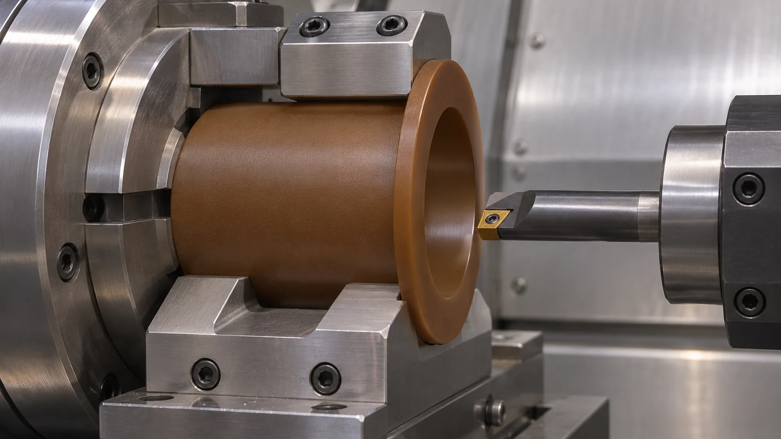 MCG’s machining guidance treats PBI among materials requiring particular attention to notch sensitivity and machining practice. Use that as a starting point for a feature-specific trial. Do not convert a stock-shape guide into a guaranteed feed, depth or surface-finish result for every geometry.
Check tool wear before accepting a change in surface appearance as a material defect. A worn edge can increase force and make a marginal exit less reliable. The qualification should include the difficult feature near the end of the intended tool interval, not just the first part cut with a fresh edge. If a cutter change restores the edge condition, retain that evidence in the process plan.
For milled pockets and mounting ears, the relevant CNC milling route should provide support and access through the sequence. A different machine axis count does not by itself resolve a fragile unsupported wall. Explain how the tool reaches the feature and what resists the cutting force.
Distinguish a removable burr from missing material
A burr leaves additional attached material. A chip or breakout removes material that should remain. Deburring may address the first condition but cannot restore the second. This distinction determines whether a local repair is acceptable or whether the feature no longer meets its geometry and damage requirements.
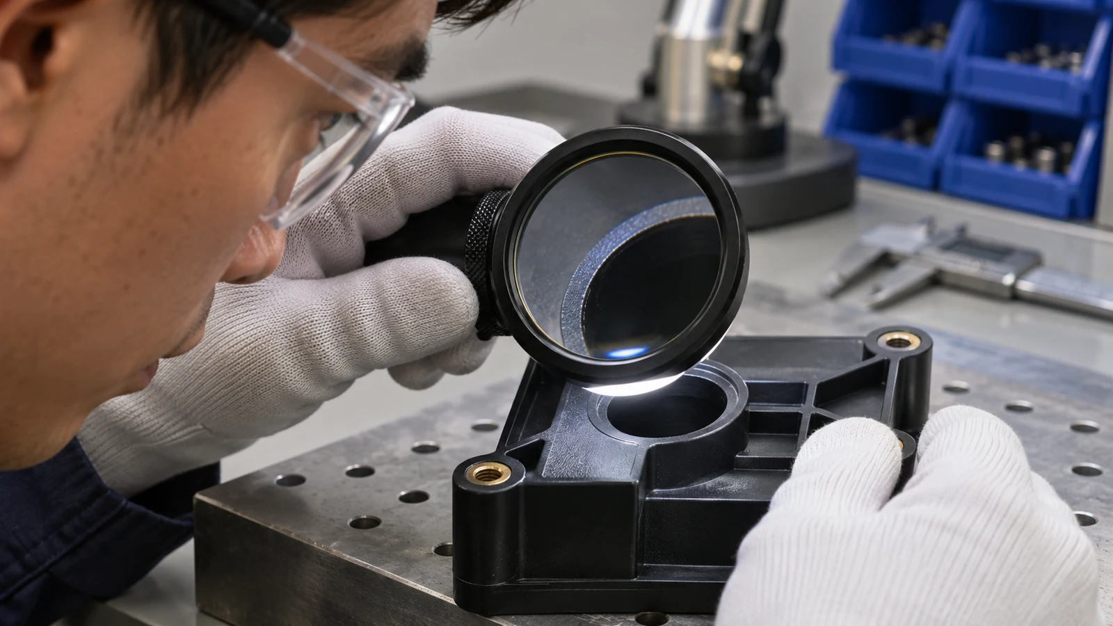 Inspect bore entrances and exits under conditions that reveal the actual edge. Decide whether magnification, profile inspection or another method is needed for the particular risk. A single roughness trace taken away from the damaged edge does not establish that the edge itself is acceptable.
| Observation | Check before rework | Acceptance implication |
|---|---|---|
| Attached projection | Whether controlled removal preserves the specified edge | Verify the edge after deburring |
| Missing corner material | Extent relative to the functional envelope | Repair needs design review; polishing does not replace material |
| Changed bore reading | Support, measuring force and conditioning state | Separate measurement response from actual geometry change |
| Repeated exit damage | Tool condition and support at breakthrough | Correct the route rather than repeatedly sorting parts |
Hypothetical spacer: a good bore with a damaged flange
Suppose the insulating spacer’s bore size is correct but the thin flange shows small edge losses after the final operation. The review first establishes whether damage is created by cutting, unloading or later handling. Examining the part only at final packing combines all three possibilities.
If damage appears at the cutter exit, the team tests support and exit direction while monitoring tool condition. If it appears during unloading, it revises the contact and release method. If damage appears only after transport, packaging needs attention. The same visible symptom can therefore require different changes; specifying a smaller tolerance on the bore would solve none of them.
This is a hypothetical analysis, not a claim of production experience. It illustrates a useful PBI machining trial: observe the vulnerable feature at the stages where damage could arise, then verify that the chosen correction preserves both the intended edge and the mating geometry.
Write the acceptance state into the order
Provide critical sizes and datum relationships, permitted edge treatments, explicit limits for chips or surface damage where needed, and the required condition for measurement. Identify storage or conditioning instructions that must be followed and any packaging needed to protect the finished geometry.
Keep component inspection separate from application validation. A conforming spacer has not thereby been approved for a particular electrical, thermal, vacuum or chemical duty. PBI machining documentation should identify the material lot, drawing revision and completed manufacturing stages without claiming performance that was never tested.
PBI machining questions
Can a blend use the same process as an unblended PBI stock shape?
Do not assume it can. Confirm the exact grade and review tool behavior, holding, conditioning and acceptance against the actual stock.
Does a high service-temperature rating justify hotter cutting?
No. A service property does not define the local cutting conditions or protect a fragile feature against force, rubbing or damage.
Can polishing make a chipped edge acceptable?
Only if the remaining geometry meets an approved requirement. Polishing can change the shape further; it cannot replace lost material.
Which feature belongs in the first trial?
The least supported or most functionally sensitive edge, including its inspection and handling. An easy external surface is a weak test of a difficult bore exit.