
CNC machining for EV components is most useful when the drawing separates functional interfaces from general geometry. A control housing needs an effective sealing interface, usable threads and walls that remain acceptable after release from the fixture. A mounting bracket needs correctly located holes, stable locating surfaces and enough room for assembly. Treating every dimension as equally critical increases machining and inspection effort without necessarily improving either part.
Compare a small aluminum electronics enclosure with its separate mounting bracket. The examples below are hypothetical design reviews, not customer case studies. They focus on enclosure and installation geometry; battery-pack safety, cooling-channel design, structural qualification and electrical compliance require their own engineering work.
Two parts, two functional maps
On the enclosure drawing, mark the perimeter gasket land, connector or cable interface, lid-fastener pattern and internal mounting points. Identify the faces that position the enclosure in the vehicle. Some outside walls may only provide an envelope and protection. They do not automatically need the flatness or finish required at a gasket land.
On the bracket, identify the plane that seats against the vehicle-side structure, the features that locate the bracket and the pattern that attaches the enclosure. Show the intended assembly clearance around fasteners, cables and tools. A hole can be within its individual size limit and still be unusable if its position or access is wrong.
| Design task | Control housing | Mounting bracket |
|---|---|---|
| Primary interface | Lid, seal and electrical-entry geometry | Locating plane and mounting pattern |
| Likely drawing focus | Sealing land, threads and released wall shape | Hole relationships, seating and assembly clearance |
| Common over-specification | Tight finish on every internal pocket | Precision requirements on clearance-only edges |
| Verification question | Do completed interfaces support the specified assembly? | Does the bracket locate without forced installation? |
The existing CNC machining for EV components context covers the wider automotive manufacturing scope. This feature map is the next level of detail: it tells the machinist which relationships must survive machining, finishing and assembly.
The enclosure starts at the lid interface
A sealing land works with a gasket, lid, fastener pattern and assembly condition. A standalone flatness requirement does not define the complete seal. Establish the seal design, required surface condition, allowed edge treatment and the datum used to position the mating parts. If a leak test is required, define its conditions and acceptance separately from the dimensional drawing.
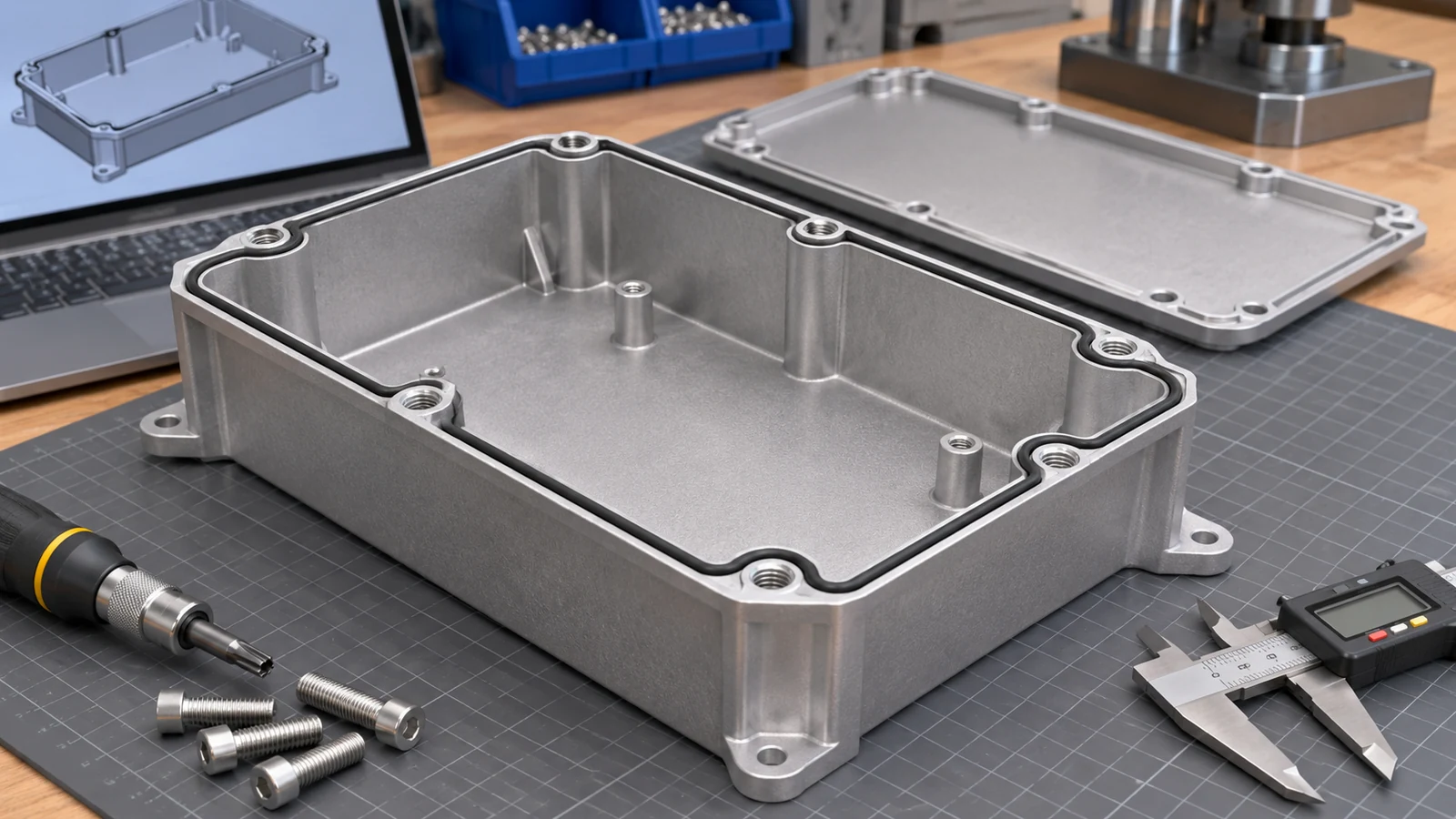 Consider the path of a scratch or tool mark across the land, not only the average roughness value. A local defect may cross the contact path while a measurement taken elsewhere appears acceptable. Likewise, a fastener boss that is displaced relative to the lid may alter how the assembly loads the seal. Inspect the relevant relationships rather than treating each feature as an unrelated dimension.
Specify connector-opening and cable-clearance requirements with their mating hardware. Avoid extending a sealing-face finish to every cavity merely because the parts share a drawing. For EV aluminum housings, distinguishing the functional surface from the general pocket gives the supplier a clearer route and a more meaningful inspection plan.
Threads and thin walls compete for the same material
A threaded boss needs enough material for the intended connection and enough tool access to produce the thread. The drawing should identify thread form and useful engagement, plus hole-bottom clearance where it matters. Do not confuse a drilled depth with usable thread depth or assume the last incomplete thread will carry the intended load.
Nearby pocket walls and mounting ears may move under cutting force or clamp load. Protolabs’ machining guidance discusses thin-wall and tool deflection as design constraints. Its particular limits describe its process offering, not a universal tolerance or minimum wall for every supplier. Review the actual material, depth, support and feature access for this enclosure.
A practical route may preserve supporting stock during roughing, balance removal where feasible and finish sensitive interfaces from a stable datum. Verify the part after release so that an enclosure is not accepted only because the fixture pulled it flat. If inspection requires an assembly fixture, define that restraint explicitly and distinguish it from a free-state requirement.
The CNC milling capability page describes the relevant manufacturing family. The drawing and process review still determine whether deep corners, narrow boss clearances or inaccessible features require changes before a stable route can be agreed.
A bracket should locate the enclosure without forcing it
For EV mounting brackets, choose datums that represent installation. If one plane seats against the vehicle structure and one hole or other feature establishes position, make that intent visible. Refer the enclosure mounting pattern to the intended reference system rather than dimensioning every hole in a long independent chain.
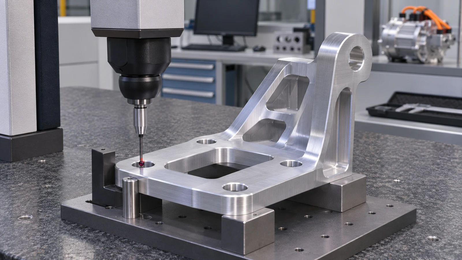 Review whether all holes are intended to locate or whether some provide assembly clearance. Making every fastener hole a locating fit can create unnecessary constraint. Slots or clearance features may be appropriate in a design, but changing them is an engineering decision; the machine shop should not enlarge holes to make a troublesome assembly fit.
Check the complete insertion path of the enclosure and the tools used to tighten it. A boss, nearby wall or cable route may block a socket even when the fastener itself fits. Include relevant mating-part geometry or an assembly view in the RFQ so that the supplier can distinguish a clearance problem from a positional tolerance problem.
Mechanical loads, vibration and fatigue requirements remain with the component and vehicle design authority. A coordinate report of the hole pattern does not establish those performance requirements. The machining review should faithfully support the approved geometry without presenting dimensional conformity as vehicle-level validation.
Put finishing changes on the drawing
Identify the exact coating or treatment, the condition in which sizes are specified and any masking needed on threads, fits, grounding contacts or sealing surfaces. Do not assume that all coatings affect every surface in the same way, or that an as-machined measurement represents the completed part.
If an enclosure requires electrical contact across selected faces, coordinate the finish and assembly requirement with the electrical design. If a bracket is primarily exposed to the environment, its protective finish may serve a different function. A cosmetic color callout cannot resolve conductivity, corrosion, fit and sealing simultaneously.
For an early build, inspect both the machined interfaces and the finished interfaces that matter. That helps determine whether a mismatch arose during cutting, treatment or assembly. Retain the drawing revision and finish specification with the record, especially when development changes are frequent.
Use the prototype to answer a production question
CNC is worth evaluating for prototypes or small batches when geometry is changing, an early assembly needs representative interfaces or tooling investment is not yet justified. It can produce a housing or bracket for checking hole relationships, lid assembly and access. What the prototype proves depends on its material, route and test conditions.
A billet-machined prototype does not reproduce every property or defect risk of a later die casting. Cast production brings its own geometry, material condition, tooling and integrity questions. When evaluating die casting with finish machining, retain the map of features that need machining and reconsider the datums used to find them in the casting.
The existing CNC and die-casting route comparison covers the wider economic decision. For these two EV parts, the useful handoff is more specific: which enclosure interfaces remain machined, which bracket features locate the assembly and which prototype conclusions require revalidation in the production route. There is no fixed annual quantity that determines the answer for every design.
Before releasing the enclosure and bracket
For the enclosure, confirm seal and lid interfaces, usable threads, allowed wall movement, finishing masks and required functional tests. For the bracket, confirm the mounting datum system, locating versus clearance features and assembly access. Apply general tolerances to the remaining geometry unless another function justifies individual control.
Provide a model, controlled drawing, mating-interface information, material and finish requirements, quantity and revision status. CNC machining for EV components becomes a better-defined purchase when the buyer can explain what each tight tolerance protects. The goal is an inspectable assembly interface, not the maximum possible number of precision callouts.
EV housing and bracket FAQs
Should the lid land and every internal pocket have the same finish?
Only if their functions require it. Define the seal-contact requirement separately from clearance pockets and cosmetic surfaces.
Can larger bracket holes solve a positional problem?
They may allow assembly but can change location, restraint or load transfer. Any change needs design approval and an updated drawing.
Does a leak-tested CNC prototype validate a later casting?
It validates only the tested configuration and conditions. Review material integrity, machining datums, finished interfaces and test requirements for the cast route.
When should dimensions be checked after coating?
When the finish can affect a controlled interface, verify the completed condition specified by the drawing. Record any earlier in-process checks separately.