
For a C-22 component with intersecting bores and a threaded port, the difficult decision is often the operation order. Hastelloy C22 machining should establish the alloy and stock condition first, then plan how each tool enters, cuts across an opening and exits without damaging a finished interface. The sequence must also leave a way to inspect internal edges. A generic nickel-alloy speed chart cannot resolve those geometric decisions.
Consider a hypothetical instrument block with a main bore, a radial connection and a threaded entrance. Drilling the radial connection first creates an interruption in the main bore. Finishing the main bore first exposes that finished surface to the later drilling exit. Neither order is automatically correct; the route must account for tool loading, burr removal, protection and verification.
Confirm C-22 before interpreting the cutting problem
Haynes identifies HASTELLOY C-22 as alloy N06022. The name is not interchangeable with C-22HS, C-276 or every nickel-chromium-molybdenum material. Confirm the specified product form and material certificate, then match the stock to the drawing revision before choosing tools or accepting a substitution.
Keep a material’s chemical-service suitability separate from the machining route. The designer or application owner must establish the intended environment and material requirement. A machine shop should not infer the fluid, temperature or corrosion allowance simply because a drawing names a corrosion-resistant alloy. The corrosion-resistant materials overview provides context, while the component specification governs the actual purchase.
Likewise, a change in stock condition can change tool behavior. A process qualified on one supplied condition does not establish a result for all bar, plate or previously worked blanks. Record the condition and blank source with the trial so that an unexpected wear trend can be investigated against a known input.
Map the interruption the tool will encounter
Draw the bore intersection in section. Identify where the cutting edge loses and regains engagement, which side of the intersecting passage remains supported and where chips can leave. A short visible opening at the outside may create a much longer interruption along an internal cutting edge.
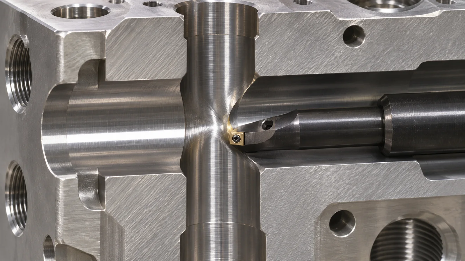 Compare the actual tool approaches rather than merely listing operations. A boring bar’s reach and stiffness, a drill’s exit into a cavity and a threading tool’s clearance create different risks. If the drawing allows a change in port direction, passage depth or nonfunctional relief, assess it before committing to an inaccessible feature.
The plan should state which reference establishes the main bore axis and how the cross-feature is located from it. Locating each operation from unrelated outside faces can produce individually acceptable dimensions with the wrong assembled relationship. The functional datum scheme needs to survive transfers between setups.
Choose the sequence that preserves the critical surface
In the instrument-block example, one option is to create the cross-feature before the final bore pass, provided the finishing tool can tolerate the interruption and remove the required material consistently. Another is to finish the bore first and use a controlled cross-hole and deburring route afterward. The second option must demonstrate that it preserves the bore and its functional edge.
Hastelloy C22 machining may combine milling, drilling and boring. The choice is driven by engagement, access and acceptance, not by a claim that one machine makes all secondary operations unnecessary. Where a feature needs a different finishing method, identify that requirement instead of hiding it inside a general machining note.
Check whether the operation order traps a burr behind an already completed feature. If the only removal method would change a sealing edge or thread, the design review should address the conflict. A final wash does not remove the need for a controlled attached-burr removal step.
Thread access is more than nominal depth
Show the required thread standard, class where applicable, useful engagement, hole-bottom clearance and any sealing function. A blind hole with insufficient space beyond useful thread depth can constrain tapping, single-point threading or thread milling differently. The supplier must know which dimensions describe useful assembly engagement and which describe tool access.
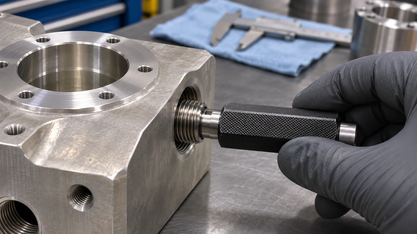 Do not treat thread milling as an automatic solution to every difficult alloy port. It changes tool motion and access requirements; it does not eliminate cutting force, work hardening or the need for a stable setup. Assess the actual diameter, reach, cutter path and inspection method before selecting the operation.
A thread gauge can answer a defined gauging question. It does not establish the condition of a sealing face, cleanliness of the blind bottom or position of the port relative to another feature. Keep those requirements distinct on the inspection plan so that a passed gauge does not become a substitute for complete acceptance.
Use wear observations to distinguish cause from symptom
Nickel-alloy machining needs attention to edge condition, rubbing, heat and rigidity. Haynes publishes machining guidance as a basis for selecting procedures. Treat those recommendations as inputs to qualification for the actual job, not a guaranteed setting for an interrupted internal cut.
When a surface degrades, record where it happens in the feature and in the tool’s service interval. A defect that repeats at a cross-hole boundary suggests a different investigation from a finish that deteriorates gradually across every part. Review engagement, tool support, coolant delivery and chip recutting with the observed edge condition.
Change one meaningful variable at a time during a controlled trial where practical. Otherwise a better-looking part may not reveal whether the improvement came from a fresh tool, altered engagement or simply a different blank. Preserve the observations that define the accepted tool-change condition.
Inspect the block as connected features
| Acceptance task | What it establishes | What still needs a separate check |
|---|---|---|
| Bore measurement | Specified size and form in the measured condition | Internal edge condition and cross-feature position |
| Thread gauging | Required thread acceptance within the gauge’s scope | Sealing surface and useful assembly clearance |
| Intersection inspection | Visible attached material or damage at the junction | Any dimension the viewing method cannot quantify |
| Specified cleaning | Residue condition under an agreed procedure | Geometry, corrosion suitability and complete assembly qualification |
Return to the hypothetical block before releasing the route. Can the inspector reach the feature that the final tool operation may damage? Does the datum used for the report represent the actual mounting interface? Are the sealing surface and useful thread still accessible after all operations? Those questions turn a tool list into an inspectable manufacturing plan.
Provide those interfaces, the material requirement, blank condition, permitted edge treatments, inspection access and required records with the RFQ. Hastelloy C22 machining can then be evaluated as a specific feature task rather than a general claim about machining all corrosion-resistant nickel alloys.
C-22 machining questions
Can a C-276 cutting recipe be reused without review?
No. Confirm C-22 stock identity and condition, then qualify the tooling and route for the actual feature. Similar alloy-family names are not a process approval.
Is drilling before boring always the better sequence?
No. It may leave the finishing tool an interrupted cut. Compare that risk with the burr and surface-protection risks of drilling afterward.
Does a leak test replace internal edge inspection?
No. A functional test under specified conditions and an inspection of attached material answer different questions. Use both when the drawing or qualification requires them.