
소개: 7075 알루미늄 가공의 궁극적인 가이드
현대 제조업에서 가장 강력하고 널리 사용되는 고성능 합금 중 하나를 마스터하기 위한 결정판 리소스에 오신 것을 환영합니다. 이 가이드는 7075 알루미늄의 잠재력을 최대한 발휘해야 하는 기계 가공 기술자, 엔지니어 및 조달 전문가를 위해 작성되었습니다. 뛰어난 강도 대 중량 비율로 유명한 이 합금은 항공우주, 방위 및 고응력 응용 분야의 초석이지만, 인상적인 특성에는 독특한 가공 요구 사항이 따릅니다. 일부 숙련된 작업자는 “6061과 똑같이 취급하며 문제를 겪은 적이 없다”고 말할 수 있지만, 더 깊고 미묘한 이해가 적절한 결과와 탁월한 결과를 구분합니다. 이 포괄적인 안내는 표면적인 조언을 넘어 재료의 야금학, 6061과 같은 일반 합금과의 중요한 차이점, 작업 현장에서 직면하게 될 실질적인 과제, 그리고 이를 극복하기 위한 검증된 전략을 탐구합니다. 7075로 첫 번째 중요한 작업을 견적하거나 더 엄격한 공차와 더 나은 공구 수명을 위해 공정을 개선하려는 경우, 다음 섹션에서는 성공에 필요한 실행 가능한 지식을 제공합니다 7075 알루미늄 가공.
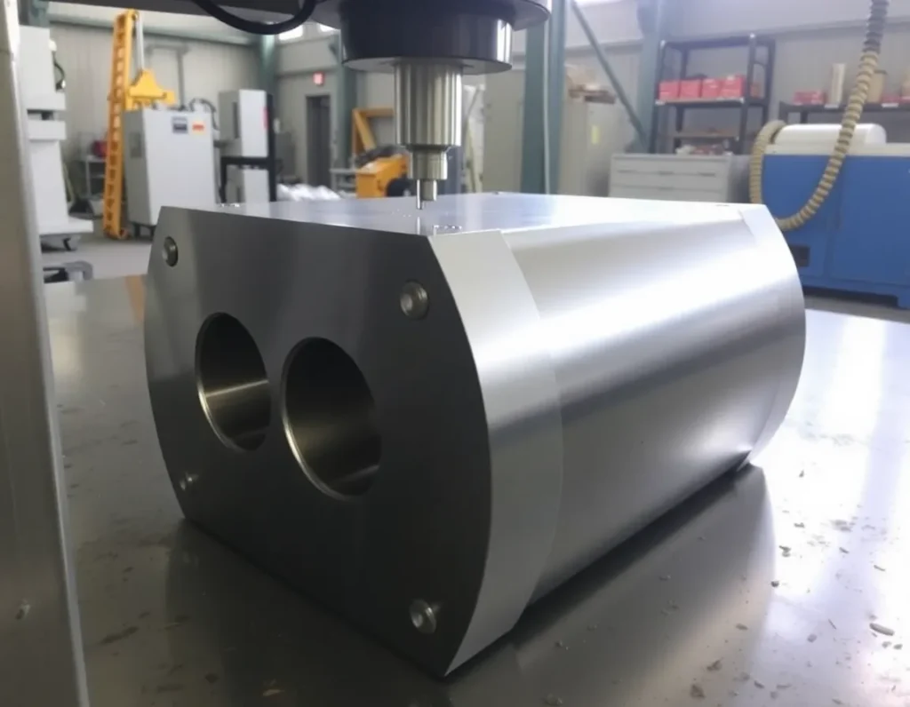
7075 알루미늄이란? 조성, 특성 및 일반적인 템퍼
핵심적으로 7075 알루미늄은 아연이 주요 합금 원소인 7xxx 계열에 속하는 냉간 처리 단조 합금입니다. 종종 “항공기 알루미늄” 또는 옛 상표명인 “지크랄(Zicral)”로 불리며, 그럴 만한 이유가 있습니다. 그 조성은 최고 성능을 위해 설계되었습니다: 일반적으로 5.1-6.1% 아연, 2.1-2.9% 마그네슘, 1.2-2.0% 구리를 함유하고 소량의 크롬을 포함합니다. 이 특정 혼합물은 열처리 중 MgZn₂ 석출물의 형성이 상당한 강화를 가져오는 치밀하고 미세한 입자 구조를 만듭니다. 그 결과 인장 강도가 83,000 psi(≥560 MPa)에 도달하고 항복 강도가 약 73,000 psi(≥450 MPa)인 합금이 탄생하여 무게는 약 1/3이면서 많은 강철과 동급입니다.
7075의 일반적인 특성은 까다로운 역할에 탁월한 선택이 되게 합니다. 우수한 강도 대 중량 비율, 양호한 피로 저항성 및 평균적인 가공성을 제공합니다. 그러나 한계를 주목하는 것이 중요합니다: 내식성은 6061과 같은 합금보다 낮으며(클래딩 또는 아노다이징으로 개선 가능), 응고 균열에 대한 높은 민감성으로 인해 일반적으로 기존 방식으로 용접할 수 없는 것으로 간주됩니다.
템퍼 이해: T6, T651, T7351 등
“템퍼” 지정은 7075를 주문할 때 중요합니다. 이는 합금의 열-기계적 처리 이력을 정의하고 기계에서의 기계적 거동을 직접 결정하기 때문입니다. 가장 흔히 접하는 템퍼는 T6(용체화 처리 및 인공 시효)입니다. 이 상태는 최고 강도를 제공하며 구조 부품에 널리 사용됩니다. T651은 T6의 하위 집합으로, 열처리 후 스트레칭으로 응력을 제거했음을 나타내며, 이는 가공 중 치수 안정성을 향상시킵니다—복잡한 부품에 필수적인 특성입니다.
또 다른 중요한 템퍼는 T7351입니다. 기계 가공 기술자 포럼에서 강조된 바와 같이, 이것은 핵심적인 차별 요소입니다. T7351 템퍼는 과시효 공정을 거치며, 이는 최대 인장 강도의 일부를 희생하여( T651보다 10% 이상 부드러워짐) 응력 부식 저항성을 극적으로 향상시킵니다. 이 과시효는 칩 형성에도 영향을 미칠 수 있습니다. 사용자들은 7075-T7351이 7075-T6의 더 취성이고 자유롭게 칩이 나오는 특성에 비해 때때로 “끈적끈적한” 느낌이 들 수 있다고 보고합니다. 이는 중요한 교훈을 강조합니다: 7075는 단일한 재료가 아닙니다. 항상 특정 템퍼를 확인하십시오. 이는 절삭 매개변수, 공구 선택, 그리고 다양한 재료 거동을 관리하기 위한 공작물 고정 전략에도 영향을 미칩니다.
7075 대 6061: 모든 기계 가공 기술자가 알아야 할 주요 차이점
둘 다 알루미늄 합금이지만, 7075와 6061은 단거리 선수와 마라톤 선수만큼 다릅니다. 이를 혼동하면 부품 불량, 공구 파손 및 부정확한 견적으로 이어질 수 있습니다. 기계 가공 기술자에게 이러한 차이를 이해하는 것은 필수입니다.
- 강도와 경도: 이것이 가장 극적인 차이입니다. 7075-T6의 인장 강도는 6061-T6의 거의 두 배입니다(83,000 psi 대 45,000 psi). 이는 7075가 훨씬 더 높은 응력을 견딜 수 있음을 의미하지만, 절삭 공구에 더 가혹하다는 의미이기도 합니다. 증가된 경도는 완성 부품으로서 우수한 내마모성에 기여합니다.
- 가공성과 칩 형성: 6061은 작고 쉽게 배출되는 칩을 생성하여 가공이 매우 쉽기로 유명합니다. 일반적인 T6 템퍼에서 7075도 잘 가공되며, 종종 미세하고 약간 더 연마성인 칩을 생성합니다. 그러나 T7351 템퍼에서 언급한 바와 같이 그 거동은 달라질 수 있습니다. 7075의 더 높은 강도는 절삭에 더 많은 마력을 필요로 하고 더 높은 절삭력을 발생시킵니다.
- Corrosion Resistance and Weldability: Here, 6061 holds the advantage. Its magnesium and silicon composition gives it very good corrosion resistance and excellent weldability. 7075 has poorer inherent corrosion resistance and is generally considered non-weldable for structural applications, often requiring mechanical fastening instead.
- Cost and Application Philosophy: 7075 is typically more expensive than 6061. The choice between them is fundamentally application-driven. Use 6061 for general-purpose parts, weldments, frames, and applications where excellent corrosion resistance and good machinability are priorities. Choose 7075 when the design is driven by maximum strength and minimum weight—think aircraft fittings, missile parts, high-performance bicycle components, and molds.
The forum advice that “If you can machine stainless, you won’t have any problems with 7075” is a useful, if rough, benchmark. It points to the need for rigid setups and appropriate tooling more akin to machining harder materials, even though 7075 is still an aluminum.
Core Challenges in 7075 Aluminum Machining: Gummy Chips, Deformation, and Tool Wear
Successfully machining 7075 aluminum requires anticipating and mitigating its specific challenges. Moving from theory to practice, these are the most common hurdles machinists face.
Gummy Chip Formation and Evacuation
While 7075-T6 is typically known for producing manageable chips, issues with gumminess arise, particularly with certain tempers like T7351 or when using suboptimal cutting parameters. Gummy chips are problematic because they don’t break cleanly. Instead, they form long, stringy ribbons that can weld themselves to the workpiece (built-up edge), wrap around the tool, and scratch finished surfaces. This is often a symptom of the material being worked, not cut—excessive heat and pressure cause the aluminum to smear rather than shear. The solution lies in maintaining sharp, polished-flute tooling, using higher surface speeds to promote clean shearing, and employing high-pressure coolant to both cool the cut and blast chips out of the way.
Dimensional Distortion and Residual Stress
This is arguably the most insidious challenge in 7075 알루미늄 가공, especially for thin-walled or complex geometries. The high strength of 7075 is achieved through intense heat treatment, which can lock significant internal (residual) stresses into the raw stock. As material is removed during machining, these stresses rebalance, causing the part to warp or twist, sometimes dramatically. A user’s query about machining a 1000x70x25mm block that deformed after unclamping is a classic example. This isn’t a failure of technique in the moment; it’s a failure to manage the material’s inherent state. Strategies to combat this include using stress-relieved stock (like T651 temper), employing symmetrical machining sequences to balance stress release, and taking light, even finishing passes to minimize the introduction of new machining stresses.
Accelerated Tool Wear
Don’t let aluminum’s soft reputation fool you. The high strength and abrasive silicon particles present in 7075 can wear out cutting tools faster than when machining 6061. Tools can experience flank wear, edge chipping, and material adhesion. As one machinist noted, “I also found if the end mill is not almost perfectly sharp/new, the results are really bad, whereas in 6061 you wouldn’t even notice.” This demands a proactive tool management strategy. Using carbide tools with sharp, polished geometries designed for aluminum is essential. Coatings like ZrN (zirconium nitride) can help reduce aluminum adhesion. Furthermore, monitoring tool life and establishing replacement schedules before surface finish degrades is critical for maintaining consistency in production runs.
By recognizing these core challenges—gummy chips, part deformation, and tool wear—you can move from reactive problem-solving to a controlled, optimized machining process. The following sections will provide the specific parameters and techniques to build this optimized approach.
Optimizing Cutting Parameters: Feeds, Speeds, and Tool Selection for 7075
Successfully machining 7075 aluminum hinges on moving beyond generic parameters to a tailored strategy that leverages its properties. While some machinists treat it “exactly the same as 6061,” a nuanced approach yields superior tool life, finish, and efficiency. The goal is to generate clean, broken chips and manage heat effectively.
For cutting speeds (SFM), a robust starting point is 300–500 SFM for carbide end mills. You can often push towards the higher end of this range with sharp, polished tools and ample coolant. However, if you encounter gummy behavior—particularly with softer tempers like T7351—dropping to the 235–300 SFM range while increasing feed per tooth can help shear the material more cleanly rather than rubbing it. As one user experimenting with T7351 found, “running the tool slower (235 sfm) with faster feeds seems to work a little better.” The key is maintaining an aggressive chip load; a feed per tooth (IPT) between 0.004″ and 0.012″ is typical, with higher feeds within that range helping to promote chip evacuation and reduce heat buildup in the cut.
Tool selection is non-negotiable. High-quality, sharp carbide end mills with 2 or 3 flutes are standard. Tools specifically designed for aluminum feature high helix angles (around 38-45 degrees) and polished flutes to prevent chip welding. Coatings like zirconium nitride (ZrN) or uncoated, polished carbide are excellent choices to minimize aluminum adhesion. Drills should be carbide-tipped or solid carbide with a high point angle (130-140 degrees) and polished flutes. For all tools, rigidity is paramount; use the shortest flute length and largest diameter shank possible to combat deflection, which can mar surface finish and accelerate tool wear.
Coolant application is not just beneficial—it’s critical. Use a flood of water-soluble coolant to manage heat, wash away chips, and prevent re-cutting. For operations where flood coolant isn’t feasible, a powerful air blast with a mist lubricant can be an alternative, though flood is preferred for optimal tool life and surface finish in 7075 알루미늄 가공.
Best Practices for Fixturing and Workholding to Minimize Deformation
The high residual stresses locked within 7075-T6 and T651 plate can be your greatest adversary when holding tight tolerances. As material is removed, these stresses rebalance, causing the part to warp, twist, or bow—sometimes dramatically. The fixturing strategy must work to both restrain the part and manage stress relief.
First, understand the stock. Whenever possible, specify stress-relieved plate (often denoted as T651, which is solution heat-treated, stretched to relieve stress, and artificially aged). This provides a more stable starting point than non-stretched material. Even with stress-relieved stock, a strategic approach to machining sequence is vital. The core principle is to remove material symmetrically and in balanced stages. Avoid hogging out one entire side of a pocket or wall while leaving the opposite side thick; instead, take alternating, even passes from both sides to allow stresses to equalize incrementally.
Fixturing must provide uniform, distributed clamping force. Use a network of clamps or a vacuum chuck to spread pressure across the workpiece, avoiding isolated points of high stress that can induce distortion when released. For thin-walled or delicate features, machine them in the final finishing pass after the bulk of the material has been removed and the part has had a chance to “move.” In some cases, it may be necessary to rough the part, unclamp it to allow it to relax, then re-fixture and take a light finishing pass to hit final dimensions.
For long, slender parts (like the mentioned 1000x70x25mm stock), additional intermediate supports are essential. Use adjustable jack screws or custom soft jaws with raised supports along the entire length to prevent sagging from its own weight or clamping pressure. The goal is to fixture the part in a state as close to its free, unstressed condition as possible.
Advanced Techniques: Drilling, Tapping, and Achieving Superior Surface Finishes
Drilling and tapping 7075 require specific techniques to avoid tool seizure, poor thread quality, and broken tools. For drilling, pecking cycles are your friend, especially for depths beyond 3x diameter. This ensures chips are cleared and coolant reaches the cutting edge. A dwell at the bottom of each peck can help break the chip. For through-holes, reduce feed slightly as the drill exits to prevent breakout burrs and potential grabbing.
Tapping 7075 can be straightforward with the right preparation. Always use a spiral-point (gun) tap for through-holes or a spiral-flute tap for blind holes to efficiently evacuate chips. The tap must be sharp and designed for aluminum. A tapping fluid or high-lubricity coolant is recommended. For critical threads, consider thread milling. This CNC technique uses a rotating end mill to generate the thread profile, offering exceptional control, no axial tool pressure (reducing breakage risk), and the ability to use the same tool for multiple hole sizes. It is highly effective for 7075 알루미늄 가공 where thread quality is paramount.
Achieving a superior surface finish often comes down to the final passes. For milled surfaces, use a light finishing pass (0.005″–0.015″ depth of cut) with a high spindle speed and a consistent, moderate feed rate. Climb milling is almost always preferred for aluminum as it produces a cleaner cut by shearing the chip away from the finished surface. Tool runout must be minimized; a wobbling tool will leave visible witness lines. For a near-mirror finish, consider using a single-purpose, sharp finishing end mill and potentially increasing the SFM while slightly reducing the feed per tooth for a finer cusp height.
Deburring is a final, critical step. The toughness of 7075 can create stubborn burrs. Manual removal with scrapers or files works, but for production, thermal energy methods (TEM) or cryogenic deburring can efficiently remove burrs from complex parts without damaging edges or affecting tolerances.
Heat Treatment and Post-Processing Considerations for 7075 Parts
7075 is a heat-treatable alloy, and understanding its tempers is crucial for both machining and final part performance. The most common temper is T6 (solution heat-treated and artificially aged to peak strength). However, as noted in the knowledge base, “The T7351 temper on 7075 is a more than 10% softer and weaker than the T651 temper.” This underscores a key point: not all 7075 is the same. T7351 (and T73) undergoes an over-aging process that sacrifices some ultimate tensile strength for dramatically improved stress-corrosion cracking resistance. It is also softer and can machine with a gummier feel.
When designing a part, select the temper based on the application’s needs: T6/T651 for maximum static strength, T73/T7351 for applications under sustained tension in corrosive environments (common in aerospace). It is generally not recommended to apply post-machining heat treatment to a finished 7075 part to change its temper, as the parts will warp significantly during the quenching process. Heat treatment should be done on the rough-machined blank, followed by finish machining to correct any distortion.
Post-processing for corrosion protection and aesthetics is common. 7075 has good anodizing characteristics. Type II (sulfuric acid) anodizing provides a decorative and moderately wear-resistant coating. For maximum corrosion protection and hardness, Type III (hardcoat) anodizing is used, though it adds significant dimensional growth (typically 0.0005″–0.002″ per surface), which must be accounted for in final part dimensions. Painting and powder coating are also viable after proper surface preparation.
Finally, for parts that have undergone significant machining, stress relieving might be considered. This involves heating the machined part to a specific temperature (below its aging temperature) for a set time to allow residual stresses from machining to relax without significantly altering the temper’s mechanical properties. This can be a valuable step for ensuring long-term dimensional stability in precision components.