
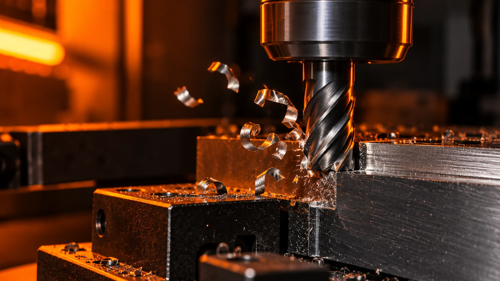
Separate speed, feed, and chip load
Surface speed describes how quickly the cutting edge moves relative to the workpiece. Spindle speed is the cutter’s revolutions per minute. Feed rate is the linear distance the tool advances per minute. Chip load per tooth estimates the feed taken by each cutting edge during one revolution. These values are related, but they are not interchangeable.
For inch-based calculations, spindle speed can be estimated from surface speed using RPM = (SFM × 12) ÷ (π × cutter diameter in inches). Feed rate is then estimated as RPM × number of effective teeth × chip load per tooth. Metric systems use compatible units; do not mix millimeters, inches, meters per minute, and feet per minute in one calculation.
The equations make the assumptions visible. They do not provide a guaranteed process recipe. Cutter maker data, grade, hardness or temper, flute geometry, coating, coolant strategy, runout, machine limits, and radial engagement all affect the usable starting range.
Build a starting calculation
- Identify the material correctly. Use the specified grade and condition, not just “aluminum” or “stainless.” Stock variation and heat treatment can change cutting behavior.
- Choose the actual tool. Record diameter, effective flute count, cutting length, overall reach, edge geometry, and toolmaker guidance.
- Set an initial surface-speed range from the tool data. Keep the cutter diameter and units consistent when converting to RPM, and respect the spindle’s maximum speed.
- Calculate table feed from the selected tooth load. Confirm the programmed feed is compatible with the machine’s acceleration and the path geometry.
- Describe engagement. State radial width, axial depth, slotting versus side milling, entry style, and whether the cut is continuous or interrupted.
- Check the weakest element. The limit may be tool strength, spindle power, holder grip, workholding, part stiffness, chip evacuation, or the feature tolerance—not the nominal horsepower.
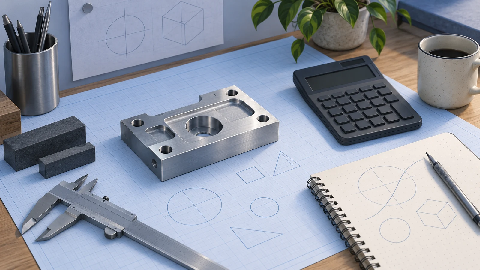
When a vendor provides a starting recommendation, keep the assumptions with the numbers. A feed-and-speed note without tool diameter, material grade, engagement, and coolant context is difficult to reproduce or troubleshoot. If a part contains both a broad roughing pass and a narrow finishing wall, do not assume one setting governs both operations.
Material-specific CNC guides for 6061 aluminum 및 7075 알루미늄 address alloy-specific considerations. Their values or recommendations should not be transferred to a different grade, cutter, or setup without checking the source assumptions.
Correct for engagement and toolpath
A full-width slot and a light radial engagement do not load a cutter in the same way. In a slot, the tool is engaged over a large part of its circumference and chips have fewer escape paths. In a side-milling path, radial engagement may be smaller, but the chip thickness varies during contact. Adaptive or trochoidal toolpaths change the engagement profile again. Therefore, feed per tooth alone does not define the actual cutting load.
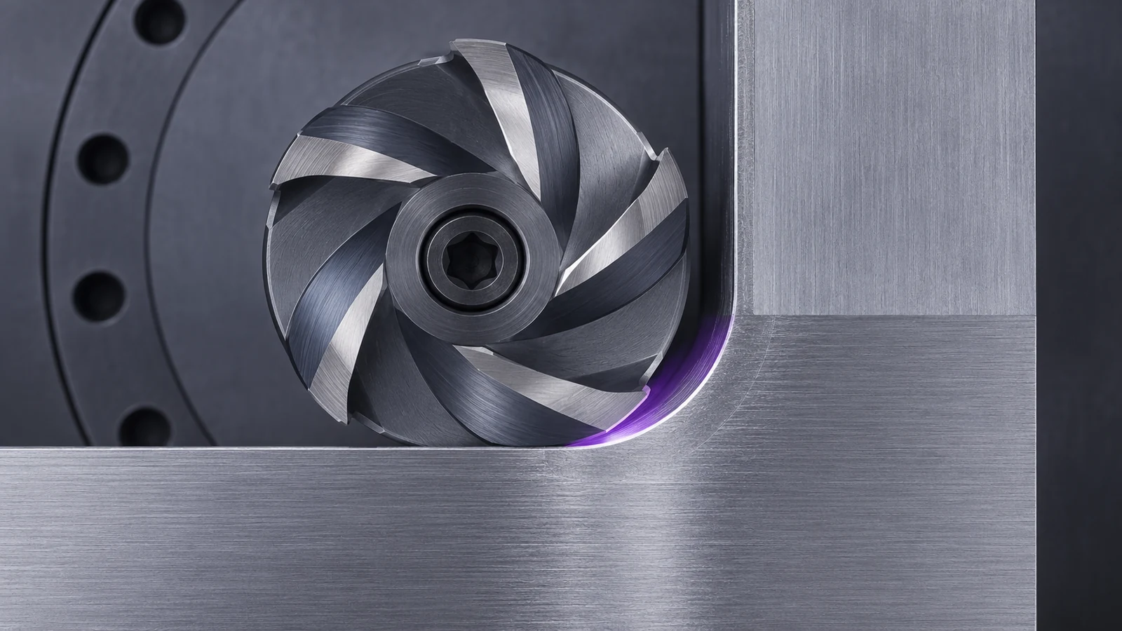
Tool reach and part stiffness matter just as much. A long stickout, a small cutter, or a thin wall can produce deflection even when the calculated feed is within a catalog range. If the feature is dimension-critical, the finishing pass may need different engagement, support, or toolpath direction than roughing. Leave a consistent allowance for finishing rather than asking the final pass to remove an unpredictable amount of stock.
Chip evacuation is a process condition, not a housekeeping detail. Recut chips can damage a surface, scratch soft material, increase heat, or cause a tool to break. Blind pockets, deep slots, and intersecting features need a plan for clearing chips. Coolant or air strategy should match material, geometry, machine setup, and tool guidance; do not assume that increasing speed alone cures a chip problem.
Read the cut before changing numbers
| Observed symptom | Possible causes to investigate | Check before changing the feed |
|---|---|---|
| Rubbing, polished edge, or heat discoloration | Low chip thickness, blunt edge, runout, unstable engagement | Tool condition, actual tooth load, radial engagement, and material condition |
| Chatter or repeating marks | Long tool reach, weak fixture, resonance, interrupted engagement | Stickout, workholding, toolpath direction, and where the marks occur |
| Excessive burrs | Tool wear, exit direction, edge geometry, unsupported material | Feature exit, edge specification, cutter sharpness, and support |
| Short tool life or chipped edges | Impact, chip recutting, excessive load, poor heat management | Entry/exit, chips, actual engagement, and tool maker’s material data |
| Size drifts across the part | Tool deflection, heat, fixture movement, or wear compensation | Datum setup, measurement sequence, temperature state, and tool wear |
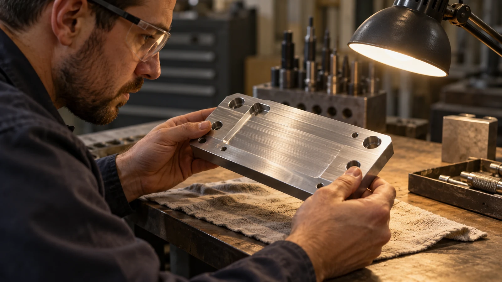
One symptom can have multiple causes. Changing feed and speed simultaneously may make the result impossible to interpret. Record one controlled change at a time where practical, and compare the same feature, measurement method, and material condition.
Validate the process on the feature
A reliable starting procedure is to define the feature and its acceptance criteria, calculate parameters from traceable tool data, review engagement and rigidity, then cut a representative pass. Inspect the result for dimension, surface condition, burrs, and repeatability—not merely whether the machine completed the toolpath.
For a prototype, record the material lot, tool identity, setup, and observed result if the intent is to learn from it. Before a production run, confirm that the same assumptions still apply: stock condition, tool replacement, fixture support, batch size, and inspection frequency can all change the process window.
When requesting a CNC milling quote, supply the drawing, material grade, critical features, finish requirements, quantity, and revision. A supplier can then review whether the proposed route and machine setup are appropriate. A generic speed chart cannot substitute for that drawing-based review.
Feeds and speeds FAQs
Is chip load the same as feed rate?
No. Chip load is an estimated feed per cutting tooth. Feed rate is the tool’s linear advance per minute and depends on spindle speed and effective tooth count.
Can one feed-and-speed chart cover every CNC milling job?
No. Charts are starting references tied to tool, material, engagement, machine, and coolant assumptions. The actual part and setup must be reviewed.
Should I raise feed when chips look thin?
Not automatically. Check runout, tooth count, actual engagement, tool wear, and whether the cutting edge is truly forming chips before changing parameters.