
A drone propeller adapter should be judged as a rotating interface, not merely as a small aluminum hub. The critical question is whether the propeller, adapter, and motor shaft share the intended axis and seat consistently after assembly. A close-looking outside diameter cannot compensate for a mismatched pilot, a tilted mounting face, or a hole pattern that pulls the propeller off-center when clamped.
Before choosing a machining route, identify what the part actually connects: a propeller to a motor shaft, a hub to a quick-release mount, or a proprietary rotor interface. Those configurations have different locating and retention features. This article focuses on the machined adapter between defined mating parts; it does not assume a universal drone standard or a particular motor architecture.
Adapter, hub, and mount are not interchangeable
In purchasing conversations, “propeller adapter” may refer to a shaft adapter, a propeller hub, or the mating half of a quick-release mount. These names should be resolved with an assembly sketch. A shaft adapter may locate on a motor shaft and carry a propeller pattern; a quick-release component adds a repeatable detachable interface; a hub may be integrated into the propeller itself. Similar labels do not guarantee compatible geometry.
That distinction changes the acceptance test. A simple adapter may be checked for shaft fit, face seating, and hole-pattern position. A detachable system also depends on engagement depth, locking behavior, and repeatability after removal. Those are assembly requirements and should not be inferred from the machined component’s appearance.
Build the part around its rotational axis
Start from the axis established by the motor shaft or bearing interface. Then define the pilot, seating face, and propeller mounting pattern relative to that axis. If the adapter is turned first and then transferred to milling for cross-holes or flats, the drawing and process plan need to preserve the turning reference during the second setup. Otherwise, each feature may meet its local dimension while the assembled rotor runs eccentrically.
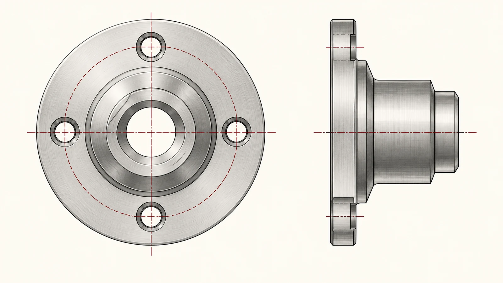
Two checks are often confused. Radial runout describes variation at a cylindrical surface relative to a chosen axis; face runout describes variation across a face as the part rotates. Neither alone proves that a propeller assembly is balanced. Balance also depends on mass distribution of the complete rotating assembly, including the propeller and fasteners, so the inspection scope must match the actual requirement.
| Interface element | What it locates or retains | Useful drawing decision |
|---|---|---|
| Shaft bore or clamp feature | Adapter relative to motor shaft | Specify fit, engagement length, and any split/clamp arrangement. |
| Axial seating face | Adapter position along the shaft and face contact | Relate face geometry to the rotational datum. |
| Pilot or register | Propeller or mating hub concentricity | State which feature is the primary radial locator. |
| Bolt pattern | Clamp load and angular orientation | Define pattern location and fastener clearance from the functional datum. |
Choose features by how the joint locates
A pilot is useful only when the mating part actually engages it and the tolerance scheme makes it the radial locator. If clearance holes are expected to locate the propeller, assembly position will depend on the hole and fastener relationship instead. Make the intended locating hierarchy clear: pilot first, face second, fasteners for clamping—or another explicitly designed scheme.
Retention deserves equal attention. Threads, a cross-hole, a clamp slot, or a shoulder each transfer load differently and create different inspection needs. Avoid making the thread serve as the locating feature unless that is deliberately part of the design. Specify thread form and depth from the assembly design, and identify any locking method separately from the machined geometry.
Turning, milling, and setup transfer
Rotationally symmetric surfaces are natural candidates for turning, while flats, slots, and bolt patterns may require milling or drilling. A combined turn-mill route can keep some features related within one workholding sequence, but only if the machine and operation plan can access them and maintain the required references. Separate processes can work just as well when the datum handoff is explicit and the inspection verifies the resulting relationship.
The relevant tradeoff is not “one setup is always better.” It is whether the chosen sequence avoids unnecessary re-location of the functional axis. For a simple cylindrical adapter, conventional turning plus a controlled secondary operation may be economical. Complex multi-face patterns or tight interface relationships may justify evaluating a different route. See CNC-Drehen und CNC-Fräsen for the site’s process context.
Material choice also affects the decision. If aluminum is specified, identify the exact alloy and temper rather than relying on “aircraft aluminum” as a purchasing description; if it is not fixed, compare the actual load, corrosion, mass, and manufacturing requirements before selecting a grade. The site’s Aluminium-Materialübersicht is a starting point, not a substitute for a design-approved material specification.
What runout checks can and cannot tell you
Runout measurement is meaningful only when the reference axis, support method, and contact location are specified. A part held on a shaft or mandrel may behave differently from one clamped by a split feature. A dial indicator reading on the outer diameter does not automatically describe the propeller seating face, and a check on the adapter alone cannot establish the balance of the assembled rotor.
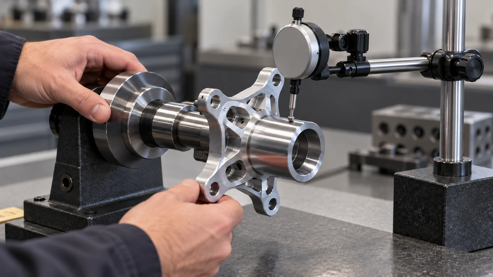
For an assembly that will rotate at speed, the product designer must define the required balance method and whether it applies to the adapter, propeller, or complete assembly. The machinist can control and report specified geometry; do not treat a dimensional inspection report as a dynamic balance certificate unless that test is explicitly performed and documented.
A compact RFQ package for the interface
Send the adapter drawing together with the mating shaft and propeller interface dimensions, a section view, material and finish requirements, fastener details, quantity, and the intended inspection condition. Mark which datum establishes the axis and which features actually locate the assembly. If the part mates with a commercial quick-release system, provide its controlled interface drawing or part number and revision; do not rely on photographs or a marketplace description.
When balance or runout is acceptance-critical, state the test article and method. This prevents two suppliers from quoting different scopes under the same short part name and gives incoming inspection a measurable basis for acceptance.