
Short answer: Invar 36’s low thermal expansion is valuable only if the part is machined, handled, and measured with its temperature and stress history in view. During Invar 36 machining, a warm part can show a different size from the same part after it returns to the inspection environment; machining also introduces local cold work and residual stress. The route should therefore control stock condition, cutting heat, intermediate stress relief when required, and the temperature at which final dimensions are accepted.
This is not a promise that a particular alloy or process will hold a metrology-grade tolerance. The drawing, material certificate, service temperature, and measurement method determine what can be claimed.
Temperature is part of the measurement
Invar 36 is a nickel–iron alloy selected for a low coefficient of thermal expansion over a defined temperature range. “Low expansion” does not mean “no movement.” A part’s dimensions still depend on temperature, and its response depends on the exact alloy condition and temperature interval. If the functional measurement is made at a different temperature from the design reference, the inspection plan should say how the part is stabilized and how the result is interpreted.
During Invar 36 machining, the cutting zone can become much warmer than the room or the part’s eventual inspection state. Avoid comparing a warm post-cut feature with a cold reference measurement. Allow the component and gage to equilibrate under a documented condition before judging a tight dimension.
Start from the stock and service-temperature requirement
Before programming, verify the material designation, product form, supplied condition, certificate, and any customer-required stabilization or stress-relief treatment. Invar 36 stock is not interchangeable with every low-expansion nickel–iron alloy. If the part must perform across a service-temperature range, define that range and the reference temperature on the drawing so the supplier and inspector use the same basis.
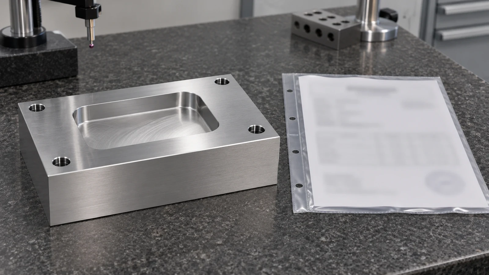
For background, the site’s metal materials overview provides the parent category. It does not establish a specific Invar 36 grade or dimensional guarantee; the purchase documentation and drawing do that.
Use staged removal when the geometry justifies it
Large pockets, thin webs, offset bores, and long mounting rails can release material unevenly. A staged route can rough the major features, allow the part to stabilize or receive an approved intermediate treatment, then finish the dimensions that control assembly. The treatment must follow the drawing or customer-approved specification; do not substitute a generic stress-relief cycle based on the alloy name.
Keep the cutting edge engaged cleanly and manage chip recutting and heat at the operation level. The exact speeds, feeds, coolant, and tool geometry depend on the supplied condition, tool maker guidance, machine rigidity, and actual part geometry. A published parameter table should not be copied blindly to a different blank or setup. If a feature is especially sensitive, leave a deliberate finish allowance and record when it is removed relative to any treatment or temperature stabilization.
For mounting plates or sensor supports, establish the locating face and hole pattern before adding nonfunctional relief. This prevents a low-expansion alloy choice from distracting from a basic datum-transfer problem.
Make inspection conditions repeatable
Record the measurement temperature, stabilization time or condition, instrument, datum setup, and whether the part is free or clamped. Use the same reference surfaces for intermediate and final checks. A fixture that forces a plate flat can conceal bow; a clamp that warms the part can create a transient reading. Measure after release and at the specified reference condition whenever free-state geometry controls performance.
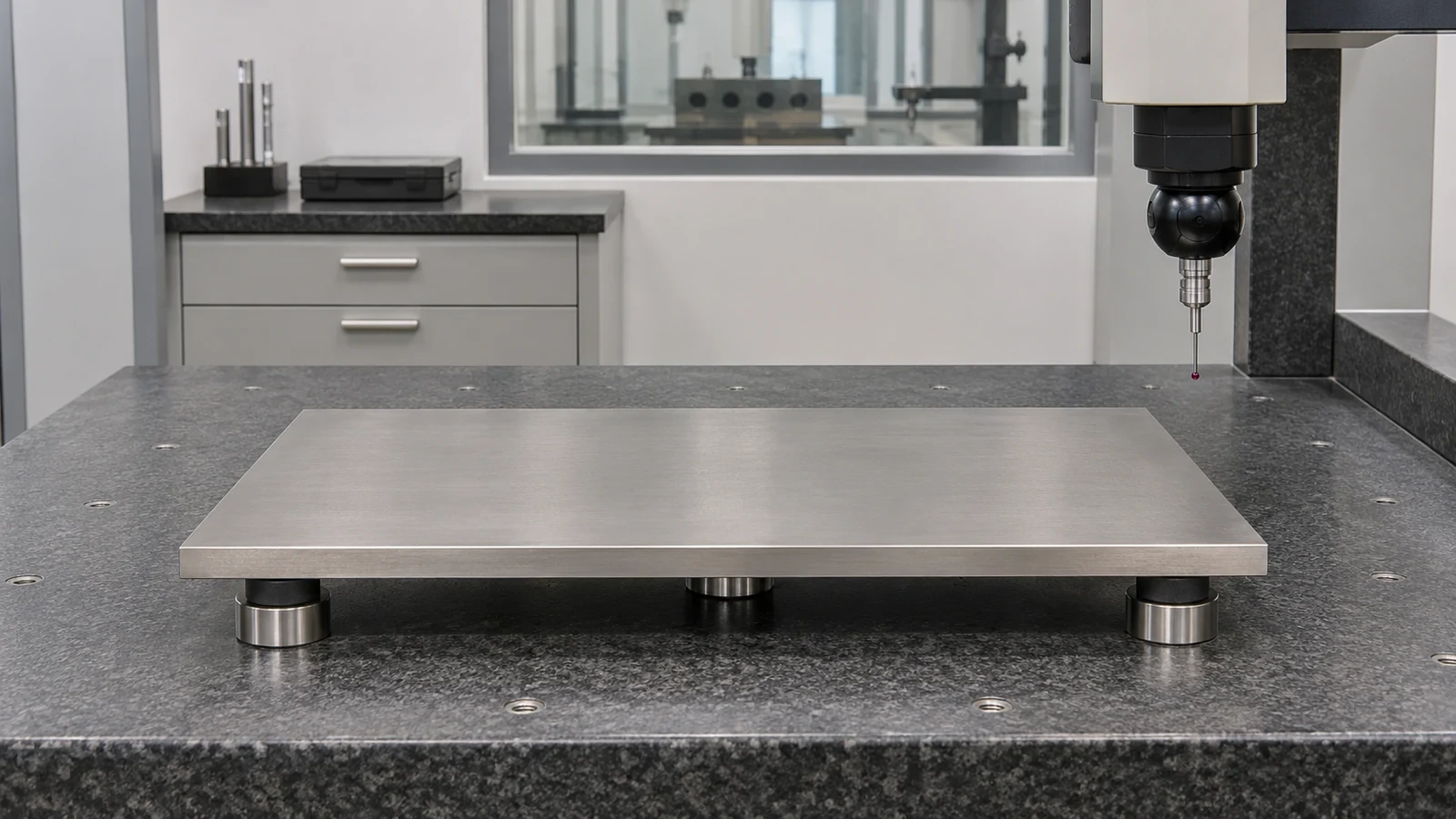
A useful acceptance plan separates three questions: Did machining produce the required geometry? Is the part at the specified inspection temperature? Does the measurement uncertainty support the stated tolerance? If any answer is unknown, a more precise tool reading alone does not resolve the uncertainty.
Specify the thermal and dimensional boundary
On the RFQ or drawing, identify the exact Invar 36 product condition, service and inspection temperatures, critical datums, free-state requirements, and any approved intermediate treatment. Define the measurement method for flatness, parallelism, or bore location and state whether the value is referenced to room temperature or another condition. If the component mates to glass, ceramic, or another metal, describe the interface requirements without assuming the CNC supplier qualifies the full assembly.
That information lets the supplier plan Invar 36 machining around both the cut and the measurement. The material’s low expansion is one input to dimensional stability; process sequence, support, thermal equilibrium, and acceptance conditions remain part of the engineering decision.